Sign-up for free online course on ANSYS simulations!
| Panel |
|---|
Problem Specification |
Step 1: Create Geometry in GAMBIT
Start GAMBIT & Select Solver
Specify that the mesh to be created is for use with FLUENT 6:
...
The boundary types that you'll be able to select in the third step depends on the solver selected. |
Strategy for creating flow field geometrygeometry
In creating the geometry for our flow field we must consider what is necessary for our model to approximate real flow. A boundary layer grows along the plate, which must satisfy the no slip condition. The flow velocity at the plate must be zero. Continuity requires that this condition gives rise to a y-velocity. Although the y-velocity is significantly smaller in magnitude than the x-velocity, it can affect the solution significantly if not taken into consideration when creating the geometry of the flow field.
...
We will put the origin of the coordinate system at the lower left corner of the rectangle that defines our flow field. The coordinates of the corners are shown in the figure below:
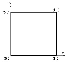
We will first create four vertices at the four corners and join adjacent vertices to get the edges of the rectangle. We will then form a face that covers the area of the rectangle.
Create Vertices
We will treat this problem as a 2-dimensional problem by assuming that the plate is infinitely wide. Let's begin by creating the vertices that define our flow region.
...
Create the vertex at the lower-left corner of the rectangle:
Next to x:, enter value 0. Next to y:, enter value 0. Next to z:, enter value 0 (these values should be defaults). Click Apply.
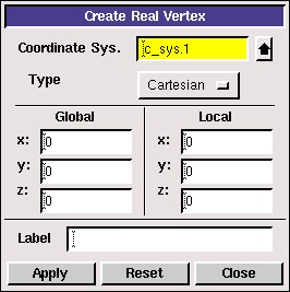
This creates the vertex (0,0,0) which is displayed in the graphics window.
...
Operation Toolpad > Global Control > Fit to Window Button 
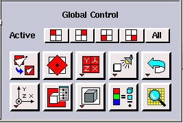
This fits the four vertices of the rectangle we have created to the size of the Graphics Window.
...
Another useful button on the Operation Toolpad is the Orient Model button  . If you click and hold the left mouse button and then move the mouse, the model will rotate 3-dimensionally. This is, of course, not usually a helpful feature when creating 2-D models in GAMBIT. Click the Orient Model button to make the z-axis normal to the page again.
Create Edges
An edge is created by selecting two vertices and creating a line between them.
...
Click the up arrow button ![]() next to the vertices box in the Create Straight Edge window.
next to the vertices box in the Create Straight Edge window.
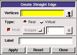
This brings up a list of vertices, from which vertices 1 and 2 can be selected. Select Vertex.1 and Vertex.2. The push the right arrow button ![]() to bring these vertices into the Picked column.
to bring these vertices into the Picked column.
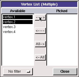
Click Close. Then click Apply in the Create Straight Edge window to create this edge.
...
(click picture for larger image)
Create Face
Operation Toolpad > Geometry Command Button  > Face Command Button
  > Form Face
...
Click the up arrow button ![]() next to the vertices box in the Create Face From Wireframe window. Then push the All right arrow button
next to the vertices box in the Create Face From Wireframe window. Then push the All right arrow button ![]() to bring these vertices into the Picked column.
to bring these vertices into the Picked column.
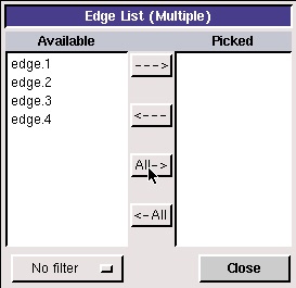
Click Close. Then click Apply in the Create Face From Wireframe window to create the face. The edges and vertices will become blue, indicating that they now form a face.
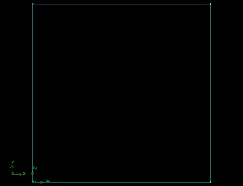
(click picture for larger image)
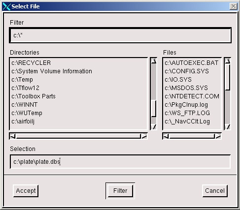
Save
Save your GAMBIT file in your working directory.
...
Find your working directory and save your GAMBIT file there. Make sure to enter the file name, plate.dbs, in the Selection box in addition to the path.