 Sign-up for free online course on ANSYS simulations!
| Panel |
|---|
Problem Specification |
...
Create the vertex at the lower-left corner of the rectangle:
Next to x:, enter value 0. Next to y:, enter value 0. Next to z:, enter value 0 (these values should be defaults). Click Apply.
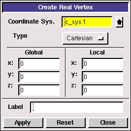
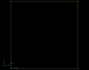
This creates the vertex (0,0,0) which is displayed in the graphics window.
...
This fits the four vertices of the rectangle we have created to the size of the Graphics Window.
...

| newwindow | ||||
|---|---|---|---|---|
| ||||
https://confluence.cornell.edu/download/attachments/90745488/01_vertices.jpg?version=2 |
Another useful button on the Operation Toolpad is the Orient Model button  . If you click and hold the left mouse button and then move the mouse, the model will rotate 3-dimensionally. This is, of course, not usually a helpful feature when creating 2-D models in GAMBIT. Click the Orient Model button to make the z-axis normal to the page again.
...
Operation Toolpad > Geometry Command Button  > Edge Command Button
  > Create Edge
 ![]()
Click the up arrow button ![]() next to the vertices box in the Create Straight Edge window.
next to the vertices box in the Create Straight Edge window.
...
This brings up a list of vertices, from which vertices 1 and 2 can be selected. Select Vertex.1 and Vertex.2. The push the right arrow button ![]() to bring these vertices into the Picked column.
to bring these vertices into the Picked column.
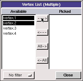
Click Close. Then click Apply in the Create Straight Edge window to create this edge.
Alternately, these vertices can be selected by holding down the Shift button and clicking on the corresponding vertices. As each vertex is picked, it will appear red in the Graphics Window. Then let go of the Shift button and click Apply in the Create Straight Edge window.
Repeat this process to create edges between vertices 2 & 3, vertices 3 & 4, and vertices 4 & 1.
(click picture for larger image)
| newwindow | ||||
|---|---|---|---|---|
| ||||
https://confluence.cornell.edu/download/attachments/90745488/01_edges.jpg?version=2 |
Create Face
Operation Toolpad > Geometry Command Button  > Face Command Button
  > Form Face
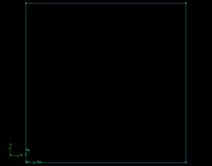
To form a face out of the area enclosed by the four lines, we need to select the four edges that enclose this area. This is done in much the same way as when we selected the vertices.
Click the up arrow button ![]() next to the vertices box in the Create Face From Wireframe window. Then push the All right arrow button
next to the vertices box in the Create Face From Wireframe window. Then push the All right arrow button ![]() to bring these vertices into the Picked column.
to bring these vertices into the Picked column.
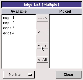
Click Close. Then click Apply in the Create Face From Wireframe window to create the face. The edges and vertices will become blue, indicating that they now form a face.
(click picture for larger image)
| newwindow | ||||
|---|---|---|---|---|
| ||||
https://confluence.cornell.edu/download/attachments/90745488/01_face.jpg?version=2 |
Save
Save your GAMBIT file in your working directory.
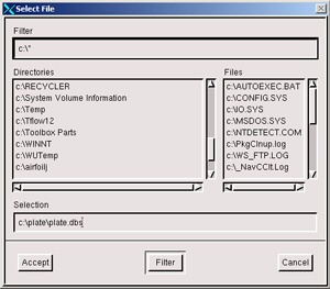
Main Menu > File > Save As... > Browse...
Find your working directory and save your GAMBIT file there. Make sure to enter the file name, plate.dbs, in the Selection box in addition to the path.
 (click picture for larger image)
| newwindow | ||||
|---|---|---|---|---|
| ||||
https://confluence.cornell.edu/download/attachments/90745488/01save_as2.jpg?version=2 |
Go to Step 2: Mesh Geometry in GAMBIT
See and rate the complete Learning Module
...