 Sign-up for free online course on ANSYS simulations!
Step 8: Postprocess the Results
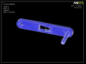
Plot Deformed Shape
Main Menu > General Postproc > Plot Results > Deformed Shape
...
This plots the deformed and undeformed shapes in the Graphics window. The maximum deformation DMX is 0.026148 inches as reported in the Graphics window. We should check that our results make sense. It appears that the boundary conditions have been satisfied as the tip of the shaft moves downward and the hole at the other end of the crank is held in place.
Animate the deformation
Utility Menu > PlotCtrls > Animate > Deformed Shape...
Select Def + undeformed and click OK. Select Forward Only in the Animation Controller. This is also a good way to check the boundary conditions have been applied correctly. Close the Animation Controller.
Plot Nodal Solution of von Mises Stress
Main Menu > General Postproc > Plot results > Contour Plot > Nodal Solu
...
To select the whole model again, go to Utility Menu > Select > Everything.
Comparing the σxx Stress with von Mises Stress
To verify that the bending stress in the crank is relatively insignificant, we can compare the element σxx solution with the elemental von Mises solution.
...
Compare the stress values with the von Mises stress. (Click on von Mises stress, then OK)
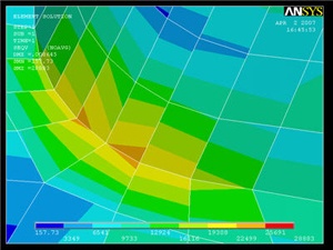
Investigate the Stress Concentration
Let's zoom in on the red area. Use the mouse wheel to zoom in and out in the view area. Some other viewing functions: Holding down the Ctrl key and the left mouse button allows you to pan the view, while holding the Ctrl key and the right mouse button allows you to rotate the view. Hold down the right mouse button and draw a rectangle to zoom in on a specific region.
...
Click on Stress, then von Mises Stress, then the OK button. In the vicinity of the cut-out corners, there are fairly significant discontinuities in the von Mises stress across adjacent elements. This suggests that we need to refine the mesh at least in this region. This is done in the next step.
Calculate Average Strain in Specified Area
In a perfect world, we would be able to validate the ANSYS results by comparing them with strain gage measurements at selected locations. We unfortunately don't have strain gage measurements for this particular geometry but will anyway show you the process by which you can calculate the average strain over an area where a strain gage would be placed. This will help prepare you to compare your ANSYS results with strain gage measurements for a different geometry for which you may have experimental data.
...