 Sign-up for free online course on ANSYS simulations!
Step 6: Specify boundary conditions
We have two loading conditions to specify. First we must fix the hole where the crank would attach to the bicycle. Then we apply our loading condition of 100 lb on the end of the shaft.
Fixed End
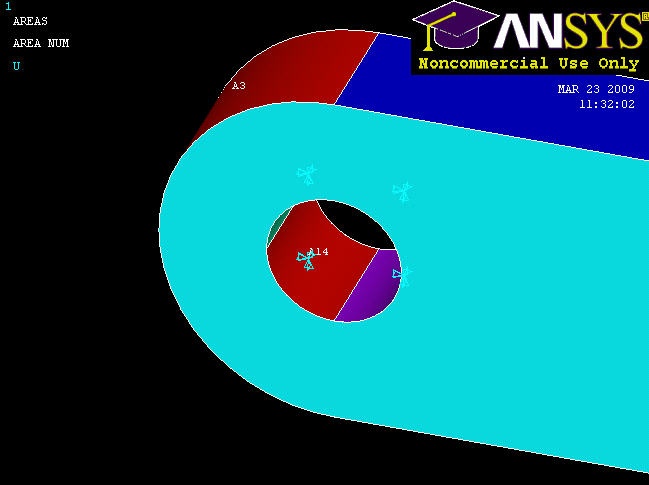
Main Menu > Preprocessor > Loads > Define Loads > Apply > Structural > Displacement > On Areas
It will be helpful to see the areas we're constraining, so select Utility Menu > Plot > Areas. We can see that the hole consists of multiple areas (4, in fact). Hold down the left-click and you can see that there are 4 surfaces that make up the inside of the hole. Pick all 4 and click OK. Select All DOF and click OK. The displacement value can be left blank as it defaults to 0. Symbols appear at the centers of each constrained area indicating that the area is constrained in three directions.

Force on Shaft
Main Menu > Preprocessor > Loads > Define Loads > Apply > Structural > Force/Moment > On Keypoints
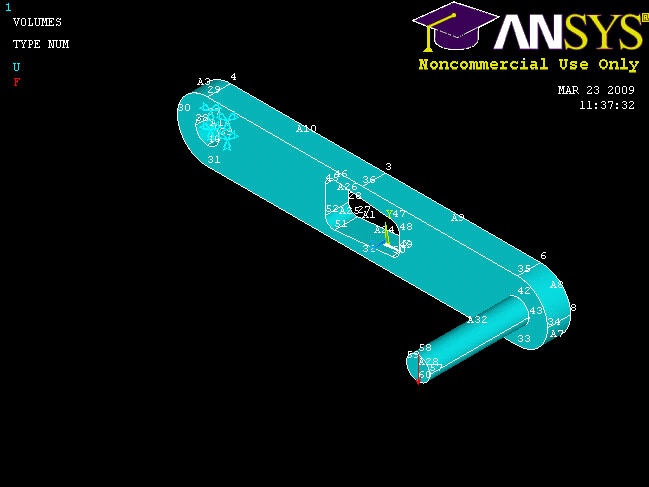
Select Utility Menu > PlotCtrls > Numbering ... and turn On Keypoint Numbers. Click OK. Notice that there is conveniently a keypoint at the tip of the shaft, and pick this point to apply the force. Click OK. From the orientation of our axes, we want a constant force in the FY direction with a value of -100. Click OK.
What the model looks like now:

Now let's see some results!
Save Your Work
Toolbar > SAVE_DB