 Sign-up for free online course on ANSYS simulations!
Author: Benjamin Mullen, Cornell University
Problem Specification
1. Pre-Analysis & Start-Up
2. Geometry
3. Mesh
4. Physics Setup
5. Numerical Solution
6. Numerical Results
7. Verification & Validation
Exercises
Comments
Geometry
For users of ANSYS 15.0, please check this link for procedures for turning on the Auto Constraint feature before creating sketches in DesignModeler.
Overview
The geometry is created in the following steps:
- Sketch: Sketch the rectangle
- Split edges: Split the horizontal edges to demarcate the unheated and heated sections.
- Dimension edges
- Create "Surface Body": Create a "Surface Body" from the sketch. This is analogous to, say, extruding a sketch to create a 3D body. We always go from a "sketch" to a "body" in DesignModeler. Here the "body" is 2D and referred to idiosyncratically as "Surface Body".
Specify Geometry as 2D
First, we need to specify that the geometry is 2-dimensional. Right click the Geometry box  and select Properties . This will open the Properties of Schematic A2: Geometry Window. Under Advance Geometry Options change Analysis Type from 3D to 2D .

After the analysis type has been set, you can dismiss the Properties window. We are now ready to launch DesignModeler, the drawing tool in ANSYS. Open DesignModeler by double-clicking the geometry box . Twiddle your thumbs until the DesignModeler window comes up. You will be prompted to choose a standard unit of measurement. Select Meter as the standard unit, and click OK .
Sketching
We want to sketch on the XY plane. To look at the XY plane, click the positive Z-Axis on the compass in the Graphics window.

Look to the left and you'll see the Tree Outline window. To sketch on the XY plane, highlight XYPlane in the Tree Outline window.To begin sketching, click on the Sketching tab at the bottom of the Tree Outline window. To draw our domain, we will use the Rectangle tool. Click on  in the Sketching Toolboxes window. In the blue graphics window, draw the rectangle by first clicking on the origin (make sure the P icon is showing, meaning the cursor is coincident with a "P"oint, in this case the origin). Then select a point in the 1st quadrant.

Because the wall has two sections, an isothermal section and a heated section, we will need to split the upper edge. To split the edge, select the Modify tab in the Sketching Toolboxes window, and select  . Next, click any point along the upper surface of the rectangle. This will split the line into 2 segments.

It turns out that to get a nice regular mesh, the bottom edge should also be split in the same way. So split the bottom edge as well (don't worry about the location, we'll adjust that next).
Now we will make the second segment of each edge to be of the same length (this will automatically ensure that the first segments are also of the same length). Go to the Constraints tab and select "Equal Length." Click on the top, right partition first. Then click on the bottom right partition. This will make these segments the same length ensuring that both the top and bottom edges are split at the same location. If you made a mistake,there is an undo button at the top left (caveat: this undo button works only in the sketching mode).
Dimensioning
The next step in creating the domain will be adding dimensions. In the Sketching Toolboxes window, select Dimensions > General . First, click the left segment of the upper edge of the rectangle, then drag the cursor to place the dimension above the line. Repeat this process for the right segment of the upper edge. Last, dimension the left edge as shown below.

We can set the dimension in the Details View window. In the Details View window, change H1 to 5.76, H2 to 2.88, and V3 to .06. You can zoom in/out using the middle mouse wheel. You can move the dimensions by selecting Dimensions > Move and then dragging the labels by grabbing them with the mouse.
Surface from Sketches
Recall that we need to create a 2D "Surface Body" from the sketch. To accomplish this, look to the top menu and select Concept > Surfaces From Sketches.

Next, click any edge on the sketch in the Graphics window. This will select the corresponding sketch. In the Details View window, select Base Objects > Apply . Now the program knows from which sketch to create the surface.

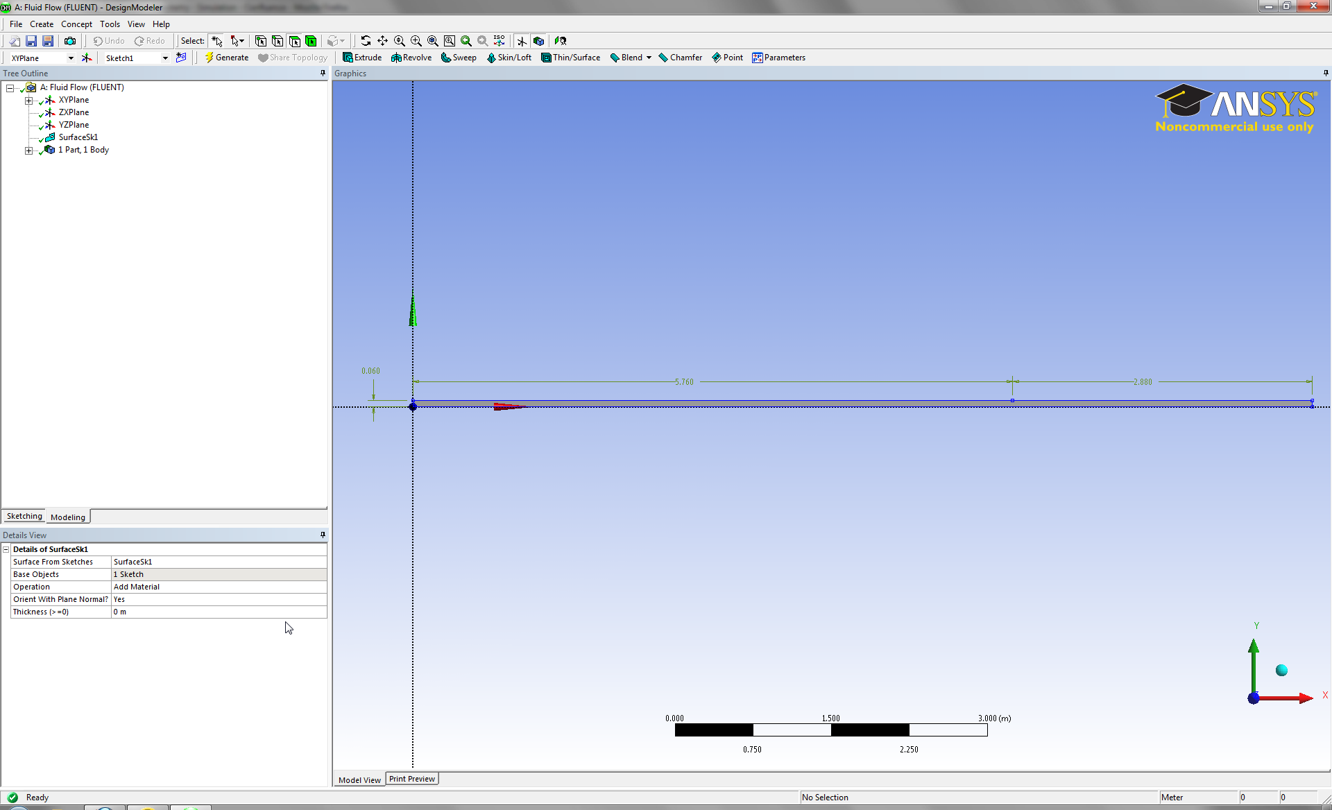
Click Generate  to create the surface. The geometry of the domain, if you have followed the tutorial successfully, should look like this:

Material
In the tree outline, expand 1 Part, 1 Body and click on Surface Body. In the Details window, next to Fluid/Solid change the material to Fluid.

Save the project by selecting File > Save Project from the main menu. Close DesignModeler. We are ready to move on to the meshing step.