 Sign-up for free online course on ANSYS simulations!
Unknown macro: {rate}
Problem Specification
1. Start-up and preliminary set-up
2. Specify element type and constants
3. Specify material properties
4. Specify geometry
5. Mesh geometry
6. Specify boundary conditions
7. Solve!
8. Postprocess the results
9. Validate the results
Problem Set 1
Problem Set 2
This is an introductory tutorial on the ANSYS software package that details how to solve a simple static truss problem. No previous knowledge of ANSYS is assumed in this tutorial.
Author: Rajesh Bhaskaran, Cornell University
Problem Specification
1. Start-up and preliminary set-up
2. Specify element type and constants
3. Specify material properties
4. Specify geometry
5. Mesh geometry
6. Specify boundary conditions
7. Solve!
8. Postprocess the results
9. Validate the results
Problem Set 1
Problem Set 2
Problem Specification
Determine the force in each member of the following truss using ANSYS 12.1. Indicate if the member is in tension or compression. The cross-sectional area of each member is 0.01 m, the Young's modulus is 200x109 N/m2 and Poisson ratio is 0.3.
The solution in ANSYS for this and subsequent tutorials is divided into the nine steps listed in the grey area above. Note that you'll need to follow these same nine steps for solving almost any problem in ANSYS or a comparable finite-element analysis package.
Go to Step 1: Start-up and preliminary set-up
See and rate the complete Learning Module
Go to all ANSYS Learning Modules
Go to Step 1: Start-up and preliminary set-up
Error formatting macro: include: java.lang.IllegalArgumentException: No link could be created for 'SIMULATION:ANSYS - Truss 1 Start-up & preliminary set-up'.
Go to Step 1: Start-up and preliminary set-up
Go to Step 2: Specify element type and constants
Error formatting macro: include: java.lang.IllegalArgumentException: No link could be created for 'SIMULATION:ANSYS - Truss 2 Specify element type and constants'.
Go to Step 2: Specify element type and constants
Go to Step 3: Specify material properties
Error formatting macro: include: java.lang.IllegalArgumentException: No link could be created for 'SIMULATION:ANSYS - Truss 3 Specify material properties'.
Go to Step 3: Specify material properties
Go to Step 4: Specify geometry
Error formatting macro: include: java.lang.IllegalArgumentException: No link could be created for 'SIMULATION:ANSYS - Truss 4 Specify geometry'.
Go to Step 4: Specify geometry
Error formatting macro: include: java.lang.IllegalArgumentException: No link could be created for 'SIMULATION:ANSYS - Truss 5 Mesh geometry'.
[Go to Step 6: Specify boundary conditions]
Error formatting macro: include: java.lang.IllegalArgumentException: No link could be created for 'SIMULATION:ANSYS - Truss 6 Specify boundary conditions'.
[Go to Step 6: Specify boundary conditions]
[Go to Step 7: Solve\!]
Error formatting macro: include: java.lang.IllegalArgumentException: No link could be created for 'SIMULATION:ANSYS - Truss 7 Solve'.
[Go to Step 7: Solve\!]
[Go to Step 8: Postprocess the results]
Error formatting macro: include: java.lang.IllegalArgumentException: No link could be created for 'SIMULATION:ANSYS - Truss 8 Postprocess the results'.
[Go to Step 8: Postprocess the results]
[Go to Step 9: Validate the results]
Error formatting macro: include: java.lang.IllegalArgumentException: No link could be created for 'SIMULATION:ANSYS - Truss 9 Validate the results'.
[Go to Step 9: Validate the results]
Problem Set 1
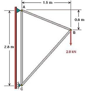
Consider the case where the displacement constraints at A and C are interchanged i.e.
- at A, only UX is set to zero
- at C, both UX and UY are set to zero
1. How would you expect the reaction forces at the supports A and C to change?
2. What can you say about how the x-component of the forces in the truss will change?
Re-solve the truss problem with the modified constraints. Fom your ANSYS solution:
1. List the reactions. Note that you can save the reaction listing as follows: in the window that comes up with the listing of the reaction forces, click on:
File > Save As
2. Determine the force in each truss member and whether the member is in tension or compression.
Tips: Start from your ANSYS solution to the truss tutorial problem but use a different job name as follows:
- Start the ANSYS Product Launcher. Specify the same directory as for the tutorial but use a different jobname. Once ANSYS comes up, select: Utility Menu > File > Resume from. Choose truss.db and click OK.
Note that you can delete constraints using:
Main Menu > Preprocessor > Loads > Define Loads > Delete
It works similar to how you apply loads.
You can plot the displacement constraints in the Graphics window as follows:
Utility Menu > Pltctrls > Symbols
Select All Applied BCs for Boundary condition symbol. Click OK.
You might have to use :
Utility Menu > Plot > Replot
or
Utility Menu > Plot > Multi-plots
for the constraint symbols to appear in your plot.
Go to Problem Set 2
See and rate the complete Learning Module
Go to all ANSYS Learning Modules
Problem Set 2
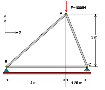
Determine the force in each member of the following truss using ANSYS. Indicate if the member is in tension or compression. Use the same LINK1 element as in the tutorial. The cross-sectional area of each member is 0.02 m2, Young's modulus is 200x109 N/m2 and Poisson's ratio is 0.3. Verify your results by calculating the forces manually.
Results
Determine the following:
1. Listing of the reactions from the ANSYS solution.
2. Listing of the element forces from the ANSYS solution. Calculate and determine the forces in each member and whether the member is in tension or compression from this ANSYS result.
3. Using your pencil-and-paper calculations verifying the ANSYS results for the member and reaction forces.
See and rate the complete Learning Module