 Sign-up for free online course on ANSYS simulations!
Step 4: Specify geometry
Note that you can import geometry from a CAD package such as Pro/Engineer or SolidWorks into ANSYS by following these instructions.
Since the geometry excluding the cutout region is symmetric with respect to the vertical centerline, we will model half of the crank and then mirror the other half to complete the crank body. Then we will create the cutout from a set of keypoints.
Create a Rectangular Area
Main Menu > Preprocessor > Modeling > Create > Areas > Rectangle > By 2 Corners
Enter the values as shown below. Click OK.

It may be helpful to turn on area numbering to identify the different areas you create.
Utility menu > PlotCtrls > Numbering ...
Check the box next to AREA Area numbers to turn on area numbering. Click OK.

Create Circular Areas
Main Menu > Preprocessor > Modeling > Create > Areas > Circle > Solid Circle
Enter the values as shown below. Click Apply. This creates the rounded end of the crank.

Enter the new set of values shown below. Click OK. This creates the area for a hole.

Your window should look something like the picture below. You can click Utility Menu > Plot > Replot or click on the Fit View  button on the right toolbar to refresh the view.

To correct any mistakes, you must click Main Menu > Preprocessor > Modeling > Delete > Areas Only and then pick each area you want to remove. The mouse pointer will show an up arrow for picking areas and a down arrow for un-picking areas. Right-click to switch between pick and unpick mode. When you have made all your selections, click OK. Click Utility Menu > Plot > Replot to refresh the view.
Add Areas
Main Menu > Preprocessor > Modeling > Operate > Booleans > Add > Areas
Pick the rectangular and large circular areas. Click OK. (This is where the area numbering may come in handy) The result should look like the image below.

Subtract Hole Area
Now we create the hole by subtracting the round area from the rest of the crank.
Main Menu > Preprocessor > Modeling > Operate > Booleans > Subtract > Areas
First pick the body of the crank and click OK. Then pick the hole, and click OK again. The result is shown below.

Reflecting the Area
To create the other half of the crank, we will reflect the current area about the Y-Z plane.
Main Menu > Preprocessor > Modeling > Reflect > Areas
Click on Pick All. The Y-Z plane is selected by default, so click OK. All that's left now is to add the two halves of the crank together.
Main Menu > Preprocessor > Modeling > Operate > Booleans > Add > Areas
Click on Pick All.


Creating Keypoints for the Cut-out Region
Since the material to be removed in the middle of the crank is an irregular shape, we will define some keypoints in order to create and subtract this area.
Main Menu > Preprocessor > Modeling > Create > Keypoints > In Active CS
Enter the values shown below and click Apply. Leave the keypoint number blank to let ANSYS automatically assign an ID number. Alternatively, you may specify your own number (as long as that keypoint isn't already taken). To see a list of existing keypoints, go to Utility Menu > List > Keypoint > Coordinates Only. The Z location is left blank because it is 0 by default.

Points to add:
(-0.7972, 0.1642)
(0.7972, 0.3248)
(0.7972, 0.9744)
(-0.7972, 1.1368)
The result:

Creating Lines and Fillets from Keypoints
Main Menu > Preprocessor > Modeling > Create > Lines > Lines > Straight Line
Select pairs of points by clicking on beginning and end keypoints. You will notice that after clicking on the first point, ANSYS will predict where you want the line to be drawn to. Select four lines to form a quadrilateral at the center of the crank, then click OK.
Don't panic if all the lines disappear. In the current view, only areas are displayed. Switch to line view by:
Utility Menu > Plot > Lines
The result:

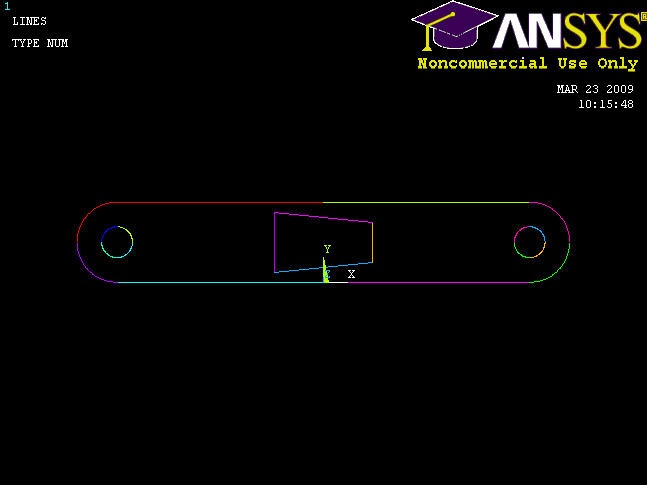
Next, we want to fillet the corners, as specified in the drawing.
You can zoom in and out by using the mouse wheel or clicking on the appropriate buttons on the right toolbar (magnifying glass with + or -).
Main Menu > Preprocessor > Modeling > Create > Lines > Line Fillet
Pick two lines that meet at a corner where you want to put a fillet, then click OK. Enter a Fillet radius of 0.177, and click Apply. Repeat for the other three corners of the quadrilateral. Compare results with image below.

Finishing the Crank Face
All that's left now is to create a new area from the filleted quadrilateral region, and then subtract it from the rest of the crank face.
Main Menu > Preprocessor > Modeling > Create > Areas > Arbitrary > By Lines
In the Pick window, select Loop. Click on any of the line segments that we have just created and the entire cutout region should be selected. Click OK. Switch back to area view by going to
Utility Menu > Plot > Areas
Subtract out the new area from the rest of the crank by the same procedure as before.
Main Menu > Preprocessor > Modeling > Operate > Booleans > Subtract > Areas
Select the rest of the crank face, then OK.
It will be helpful to hold down the left mouse-button while picking an area, as an area changes color when it is selected. Move the pointer until the desired area is highlighted, then release the button. Finally, select the new cut-out area, then press OK again.
The result:

Creating the Volume
We will now make the face 3-D by extruding it by a given offset distance, similar to modeling in CAD.
Main Menu > Preprocessor > Modeling > Operate > Extrude > Areas > By XYZ Offset
Click Pick All. In the following window, change the DZ offset to 0.5. Click OK. To see your finished work, go to
Utility Menu > Plot > Volumes
Then click on the isometric view button  on the right toolbar.


Creating the Pedal Shaft
Main Menu > Preprocessor > Modeling > Create > Volumes > Cylinder > Solid Cylinder
Enter the following values and press OK.

We must now glue the shaft to the crank. The reason for using "glue" instead of performing a boolean add on the volumes is to maintain two discrete parts. This provides more flexibility in modeling, as it can allow for different materials and meshes. Note: If glue is not used, the two pieces will be independent of each other and the solution will be incorrect.
Main Menu > Preprocessor > Modeling > Operate > Booleans > Glue > Volumes
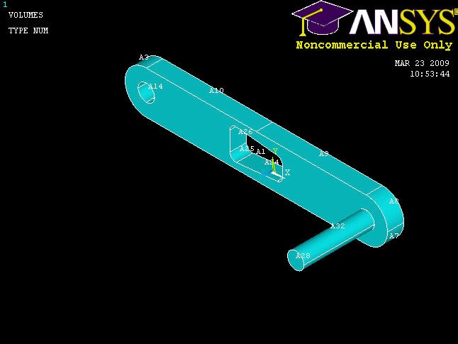
Click Pick All to glue our two volumes together. Note that there are no visual indicators of whether or not the volumes have been glued. You should check the Command Window and look for the "GLUE VOLUMES" command.

Your complete crank model should now look like this:

Save Your Work
Toolbar > SAVE_DB