 Sign-up for free online course on ANSYS simulations!
Step 1: Create Geometry in GAMBIT
If you wish to skip the steps for grid creation, you can download the mesh file here (right-click and select Save As...) and go to Step 4. |

This tutorial leads you through the steps for generating a mesh in GAMBIT for an airfoil geometry. This mesh can then be read into FLUENT for fluid flow simulation.
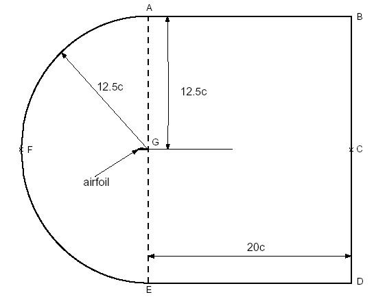
In an external flow such as that over an airfoil, we have to define a farfield boundary and mesh the region between the airfoil geometry and the farfield boundary. It is a good idea to place the farfield boundary well away from the airfoil since we'll use the ambient conditions to define the boundary conditions at the farfield. The farther we are from the airfoil, the less effect it has on the flow and so more accurate is the farfield boundary condition.
The farfield boundary we'll use is the line ABCDEFA in the figure above. c is the chord length.
Start GAMBIT
Create a new directory called airfoil and start GAMBIT from that directory by typing gambit -id airfoil at the command prompt.
Under Main Menu, select Solver > FLUENT 5/6 since the mesh to be created is to be used in FLUENT 6.0.
Import Edge
To specify the airfoil geometry, we'll import a file containing a list of vertices along the surface and have GAMBIT join these vertices to create two edges, corresponding to the upper and lower surfaces of the airfoil. We'll then split these edges into 4 distinct edges to help us control the mesh size at the surface.
The file containing the vertices for the airfoil can be downloaded here: naca4412.dat (right click and select Save As...)
Let's take a look at the naca4412.dat file:
255    2

0    0    0

-0.00019628    0.001241474    0

-0.000247836    0.001759397    0

-0.000275577    0.002158277    0

-0.000290986    0.002495536    0

-0.000298515    0.002793415    0

-0.000300443    0.00306332    0
The first line of the file represents the number of points on each edge (255) and the number of edges (2). The first 255 set of vertices are connected to form the edge corresponding to the upper surface; the next 255 are connected to form the edge for the lower surface.
The chord length, c for the geometry in naca4412.dat file is 1, so x varies between 0 and 1. If you are using a different airfoil geometry specification file, note the range of x values in the file and determine the chord length c. You will need this later on.
Main Menu > File > Import > ICEM Input ...
For File Name, browse and select the naca4412.dat file. Select both Vertices and Edges under Geometry to Create: since these are the geometric entities we need to create. Deselect Face. Click Accept.

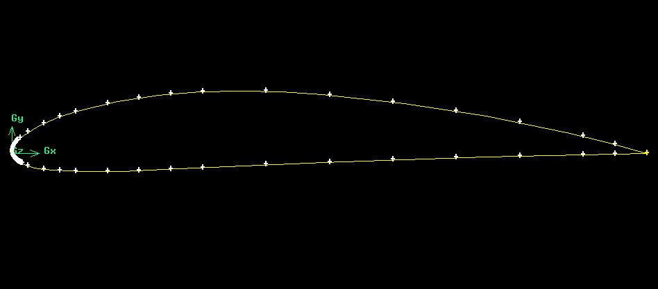
We have more points around the nose area because of the high curvature around the nose.
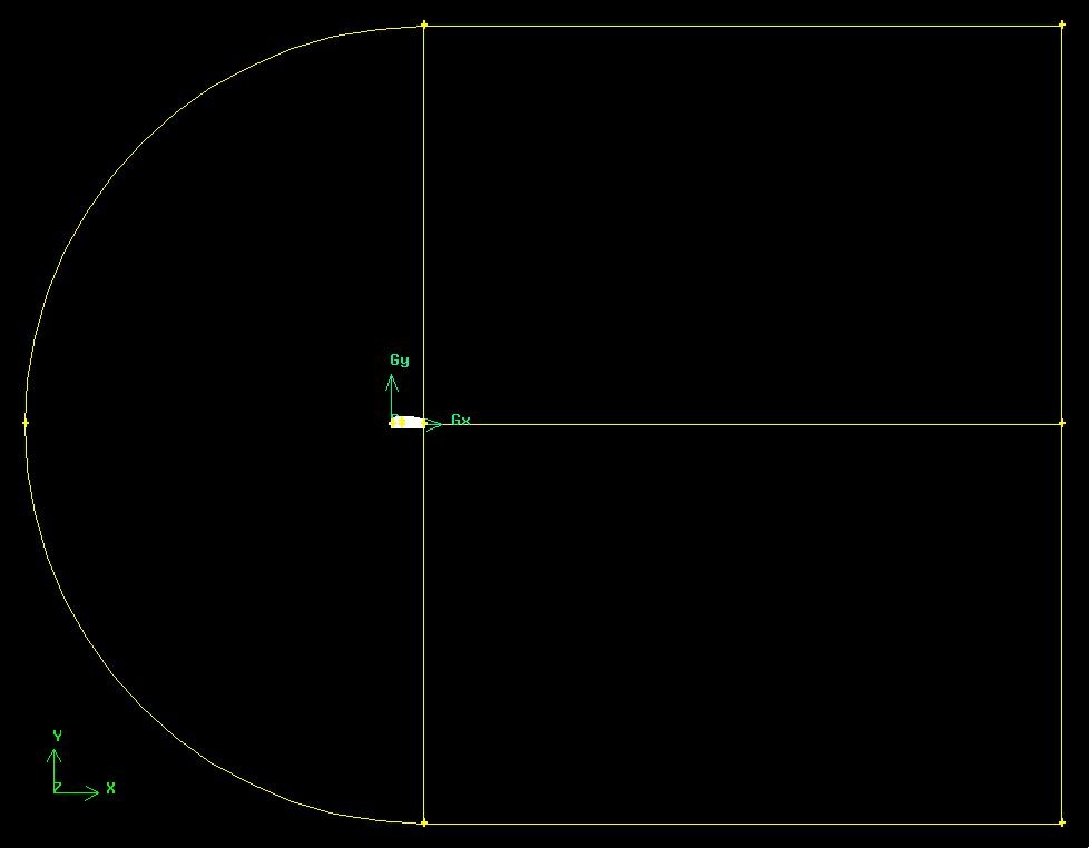
Create Farfield Boundary
Next, we will create the following farfield boundary. This picture of the

will be handy.
We will create the farfield boundary by creating vertices and joining them appropriately to form edges.
Operation Toolpad > Geometry Command Button  > Vertex Command Button
  > Create Vertex
Create the following vertices by entering the coordinates under Global and the label under Label:
Label |
x |
y |
z |
A |
c |
12.5c |
0 |
B |
21c |
12.5c |
0 |
C |
21c |
0 |
0 |
D |
21c |
-12.5c |
0 |
E |
c |
-12.5c |
0 |
F |
-11.5 |
0 |
0 |
G |
c |
0 |
0 |
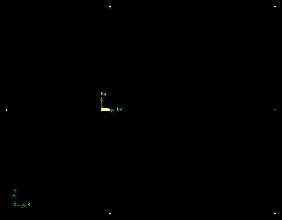
Click the FIT TO WINDOW button to scale the display so that you can see all the vertices. The resulting image should look like this:

Now we can create the edges using the vertices created.
Operation Toolpad > Geometry Command Button > Edge Command Button  > Create Edge
Create the edge AB by selecting the vertex A followed by vertex B. Enter AB for Label. Click Apply. GAMBIT will create the edge. You will see a message saying something like "Created edge: AB'' in the Transcript window.
Similarly, create the edges BC, CD, DE, EG, GA and CG. Note that you might have to zoom in on the airfoil to select vertex G correctly or click on the  to select the vertices from the list and move them to the picked list. The rest of the tutorial will use this method for vertices selection.
Next we'll create the circular arc AF. Right-click on the Create Edge button and select Arc.

In the Create Real Circular Arc menu, the box next to Center will be yellow. That means that the vertex you select will be taken as the center of the arc. Select vertex G and click Apply. Now the box next to End Points will be highlighted in yellow. This means that you can now select the two vertices that form the end points of the arc. Select vertex A and then vertex F. Enter AF under Label. Click Apply.
If you did this right, the arc AF will be created. If you look in the transcript window, you'll see a message saying that an edge has been created.
Similarly, create an edge corresponding to arc EF.

Create Faces
The edges we have created can be joined together to form faces. We will need to define three faces as shown in the image above. Two rectangular faces, rect1 and rect2 lie to the right of the airfoil. The third face, circ1 consists of the area outside of the airfoil but inside of the semi-circular boundary.
Operation Toolpad > Geometry Command Button > Face Command Button  > Form Face
This brings up the Create Face From Wireframe menu. Recall that we had selected vertices in order to create edges. Similarly, we will select edges in order to form a face.
To create the face rect1, select the edges AB, BC, CG, and GA. Enter rect1for the label and click Apply. GAMBIT will tell you that it has "Created face: rect1'' in the transcript window.
Similarly, create the face rect2 by selecting ED, DC, CG and GE.
To create the last face we will need to make two separate faces, one for the outer boundary and one for the airfoil and then subtract the airfoil from the boundary . Create semi-circular face circ1 by selecting GA, AF, FE and EG and enter circ1 for the label. Create the face for the airfoil by selecting corresponding edges. Subtract the airfoil from circ1.
Operation Toolpad > Geometry Command Button > Face Command Button
right click on the Boolean Operations Button  and select Subtract
The Face box will be highlighted yellow. Shift click to select circ1, the outer semi-circular boundary. Then select the lower box labeled Subtract Faces which will allow you to select faces to subtract from our outer boundary. Select the airfoil face and click apply.
Go to Step 2: Mesh Geometry in GAMBIT.