 Sign-up for free online course on ANSYS simulations!
Mesh
Default Mesh
In this section the default mesh will be generated. In order to generate the default mesh first click on Mesh, then click on Update as shown in the image below.

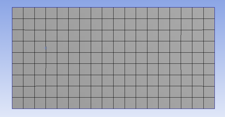
You should then obtain the following mesh.

Mapped Face Meshing
For this particular problem, we are interested in creating a grid style of mesh that can be mapped to a rectangular domain. This meshing style is called Mapped Face Meshing. In order to incorporate this meshing style (Click) Mesh Control > Mapped Face Meshing as can be seen below.

Now, the Mapped Face Meshing still must be applied to the geometry. In order to do so, first click on the surface body(filled rectangle), which should then highlight green. Next, (Click) Apply in the Details of Mapped Face Meshing table, as shown below.

This process is shown in the link below.
Now, generate the mesh by clicking Update.
Edge Sizing
The desired mesh has a specific number of divisions in the x direction and a specific number of divisions in the y direction. In order to obtain the specified number of divisions Edge Sizing must be used. The divisions in the x direction will be specified first. Now, an Edge Sizing needs to be inserted. First, (Click) Mesh Control > Sizing as shown below.

Now, the geometry and the number of divisions need to be specified. First (Click) Edge Selection Filter. Then hold down the "Control" button and then click the bottom and top edge of the rectangle. Both sides should highlight green. Next, hit Apply under the Details of Sizing table as shown below.

Now, set Type to Number of Divisions as shown in the image below.

Then, set Number of Divisions to 50 as shown below.

Next, set the Behavior to Hard as shown in the image below. This step will disable the ANSYS Mesher from overwriting any of our edge sizing specifications.
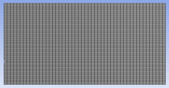
At this point, the edge sizing in the the y direction will be specified. Follow the same procedure as for the edge sizing in the x direction, starting first by selecting (Click) Mesh Control > Sizing. Select only the left side instead of the top and bottom and set the number of divisions to 60. Remember to set the Behavior to Hard. Then, click Update to generate the mesh with the new specifications. You should obtain the following mesh.

Your mesh should now have 3,000 elements (50x60). In order to check how many elements your mesh has, expand Statistics under "Details of Mesh" as shown below.

Make sure that you also have 3,000 elements.
Edge Sizing Biasing
We would like to have more elements in the region very close to the flate plate and less elements in the far field. In order to do this, we must bias the edge sizing. First, click on Edge Sizing 2, then click on Bias Type and set it to the first option as shown below.

Next, set the Bias Factor to 70 as shown below. The Bias Factor is defined in this case to be the ratio of the longest division and the shortest division. That is, the last division will be seventy times longer than the length of the first division.

Now, the biasing needs to be specified for the right side of the geometry. In order to incorporate the biasing on the right side a new Edge Sizing needs to be implemented. First, (Click) Mesh Control > Sizing. Then, select and apply the right side of the geometry. Then, change Type to Number of Divisions and set Number of Divisions to 60. Next, set Behavior to Hard and set Bias Type to the second option, as shown below.
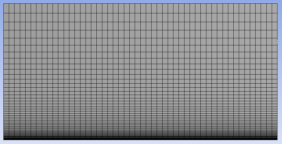
Then, set the Bias Factor to 70. Lastly, click Update to generate the new mesh. You should obtain the following mesh.

Create Named Selections
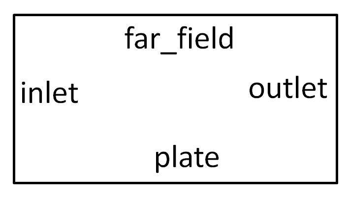
Here, the edges of the geometry will be given names so one can assign boundary conditions in FLUENT in later steps. The left side of the geometry will be called "inlet" and the right side will be called "outlet". The top side of the rectangle will be called "far_field" and the bottom side of the rectangle will be called "plate" as shown in the image below.

In order to create a named selection first (Click) Edge Selection Filter. Then click on the left side of the rectangle and it should highlight green. Next, right click the left side of the rectangle and choose Create Named Selection as shown below.

Select the left edge and right click and select Create Named Selection. Enter "inlet" and click OK, as shown below.

Now, create named selections for the remaining three sides and name them according to the diagram. Once you have created all four named selections, expand Named Selections and you should see the four named selections, as shown below.

Save, Exit & Update
First save the project. Next, close the Mesher window. Then, go to the Workbench Project Page and click the Update Project button.