 Sign-up for free online course on ANSYS simulations!
Geometry
The geometry is a rectangle of length 1 m and height 0.5 m. The following instructions are for creating the geometry in DesignModeler which is now a legacy tool. SpaceClaim is the recommended geometry engine. The steps for creating a rectangle using SpaceClaim are covered in Dr. Bhaskaran's free online course at edX.org. Go to section 4.3 Laminar Pipe Flow > Geometry. Don't forget to use the dimensions for this problem while creating the rectangle in SpaceClaim.
Saving
It would be of best interest, to save the project at this point. Click on the "Save As.." button,  , which is located on the top of the Workbench Project Page . Save the project as "FlatPlateFlow" in your working directory. When you save in ANSYS a file and a folder will be created. For instance if you save as "FlatPlateFlow", a "FlatPlateFlow" file and a folder called "FlatPlateFlow_files" will appear. In order to reopen the ANSYS files in the future you will need both the ".wbpj" file and the folder. If you do not have BOTH, you will NOT be able to access your project.
Fluid Flow(FLUENT) Project Selection
On the left hand side of the workbench window, you will see a toolbox full of various analysis systems. To the right, you see an empty work space. This is the place where you will organize your project. At the bottom of the window, you see messages from ANSYS. Left click (and hold) on Fluid Flow (FLUENT) , and drag the icon into the empty space in the Project Schematic . Your ANSYS window should now look comparable to the image below.

Since we selected Fluid Flow(FLUENT), each cell of the system corresponds to a step in the process of performing CFD analysis using FLUENT. Rename the project to "FlatPlate". We will work through each step from top down to obtain the solution to our problem.
Analysis Type
In the Project Schematic of the Workbench window, right click on Geometry and select Properties , as shown below.

The properties menu will then appear to the right of the Workbench window. Under Advance Geometry Options , change the Analysis Type to 2D as shown in the image below.

Launch Design Modeler
In the Project Schematic , double click on Geometry to start preparing the geometry. At this point, a new window, ANSYS Design Modeler will be opened. You will be asked to select desired length unit. Use the default meter unit and click OK .
Creating a Sketch
Start by creating a sketch on the XYPlane . Under Tree Outline , select XYPlane , then click on Sketching right before Details View . This will bring up the Sketching Toolboxes .
Click on the +Z axis on the bottom right corner of the Graphics window to have a normal look of the XY Plane.
In the Sketching toolboxes, select Rectangle . In the Graphics window, create a rough rectangle by clicking once on the origin and then by clicking once somewhere in the positive XY plane. (Make sure that you see a letter P at the origin before you click. The P implies that the cursor is directly over a point of intersection.) At this point you should have something comparable to the image below.

Dimensions
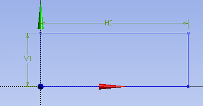
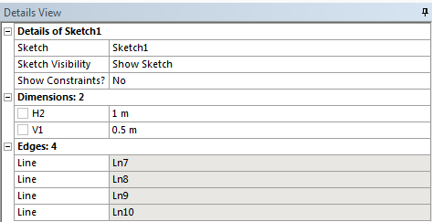
At this point the rectangle will be properly dimensioned. Under Sketching Toolboxes , select Dimensions tab, use the default dimensioning tools. Dimension the geometry as shown in the following image.

Under the Details View table (located in the lower left corner), set V1=0.5m and set H2=1m, as shown in the image below.

Surface Body Creation
In order to create the surface body, first (Click )Concept > Surface From Sketches as shown in the image below.

This will create a new surface SurfaceSK1 . Under Details View , select Sketch1 as Base Objects . Finally, click Generate to generate the surface.
At this point, you can close the Design Modeler and go back to Workbench Project Page . Save your work thus far in the Workbench Project Page.