 Sign-up for free online course on ANSYS simulations!
Authors: John Singleton and Rajesh Bhaskaran, Cornell University
Problem Specification
1. Pre-Analysis & Start-Up
2. Geometry
3. Mesh
4. Physics Setup
5. Numerical Solution
6. Numerical Results
7. Verification & Validation
Exercises
Comments
THIS IS AN OLDER VERSION. PLEASE USE CURRENT VERSION OF THIS PAGE.
Geometry
For users of ANSYS 15.0, please check this link for procedures for turning on the Auto Constraint feature before creating sketches in DesignModeler.
Strategy for Geometry Creation
In order to create the desired geometry we will first create a surface body for the cylinder. Next, we will create a surface body for the outer boundary as a "frozen body", so that it doesn't merge with the first surface body. Then, we will use a boolean operation to subtract the small surface body from the large surface body. At this point, we will have the surface body of the outer boundary with a hole in the middle where the cylinder is. Lastly, we will project a vertical line on to the geometry, so that radial edge sizing can be implemented in the meshing process.
Fluid Flow(FLUENT) Project Selection
Drag Fluid Flow(FLUENT) into the Project Schematic window.
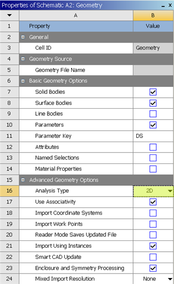
Analysis Type
(Right Click) Geometry > Properties
Set Analysis Type to 2D
Launch Design Modeler
(Double Click) Geometry
Create Inner Circle and Dimension
Create a circle, centered around the origin in the xy plane. Set the diameter of the circle to 1m.
Inner Circle Surface Body Creation
Concept > Surfaces From Sketches .
Set the Base Object to Sketch 1 (located underneath XYPlane in the Tree). You can do this by clicking within the tree or you can click on the circle to select Sketch 1. Then click Apply next to Base Object .
Click Generate
Create New Sketch in the XY Plane
In this step we will create a new sketch in the XY Plane. This step is required for the boolean operation that we will carry out later in the geometry process. It allows us to create two distinguishable geometries, in the xy plane.
Click on XYPlane in the Tree Outline and it should highlight blue. Then click on the New Sketch button,  .
.

Create Outer Circle and Dimension
Now, create a circle centered around the origin in Sketch 2 . Set the diameter of the circle to 64m. You can click the "fit to window" button shown below to see both circles.

Outer Circle Surface Body Creation
In this step the Surface Body will be created as a frozen, such that it does not merge with the inner circle surface body.
Concept > Surfaces From Sketches .
Set the Base Object to Sketch 2 (located underneath XYPlane in the Tree). You can do this by clicking within the tree or you can click on the outer circle to select Sketch 2. Then click Apply next to Base Object .
Then set Operation to Add Frozen as shown in the image below.
 \
\
Then, click Generate

Carry Out Boolean Operation: Subtraction
In this step, the inner circle will be subtracted from the outer circle in order to obtain the desired geometry.
Create > Boolean .
First, set Operation to Subtract . Next, use the face selection filter,  , to apply the outer circle surface body as the Target Body . Then, use the face selection filter, , to apply the inner circle surface body as the Tool Body . In order to select inner circle which overlaps with the outer circle, you may have to click on the planes to the lower left as shown below.

Lastly, click Generate . At this point if you zoom into the center of the circle you should see the 1m diameter hole, as shown below.

Create a Bisecting Line
The purpose of this step and the following two steps is to imprint a line onto the geometry that will, allow for radial edge sizing in the meshing step.
Click on XYPlane in the tree and it should highlight blue. Then, click the new sketch button, . In the new sketch draw a line on the y axis that goes through both of the concentric circles. Make sure that it is coincident to the y axis. Then trim the line segments that lay inside of the inner circle and the line segments that lay outside of the outer circle. This, is carried out by using the Trim feature located in the Modify portion of Sketching .
Line Body Creation
Concept > Lines From Sketches .
Set the Base Object to Sketch 3. (located underneath XYPlane in the Tree). Click Generate
Projection
Tools > Projection .
Apply the two lines that you created to edge and apply the surface body to target. You must do these steps by using the line selection filter and the surface selection filter. For the two lines hold down control to select them both. Click Generate .
Suppress Line Bodies
Under "Tree Outline", expand "3 Parts, 3 Bodies". Find the two line bodies, right click and choose suppress.

Change type to "Fluid"
Under "Tree Outline", expand "3 Parts, 3 Bodies" and select "Surface Body". Then set the type "Fluid/Solid" to Fluid.

Close Design Modeler and Save Project
To save the project, first close the design modeler and at the workbench window, go to files -> archive. If you choose "save", it will save it as two items: a file and a folder whereas the archive option saves it as one integrated item.
