 Sign-up for free online course on ANSYS simulations!
Unable to render {include} The included page could not be found.
Author: Ranjith Tirunagari, Cornell University
Problem Specification
1. Pre-Analysis & Start-Up
2. Geometry
3. Mesh
4. Setup (Physics)
5. Solution
6. Results
7. Verification & Validation
Step 2: Geometry
Saving
It would be of best interest, to save the project at this point. Click on the "Save As.." button,  , which is located on the top of the Workbench Project Page. Save the project as "TurbulentPipeFlow" in your working directory. When you save in ANSYS, a file and a folder will be created. For instance if you save as "TurbulentPipeLES", a "TurbulentPipeLES.wbpj" file and a folder called "TurbulentPipeLES_files" will appear. In order to reopen the ANSYS files in the future you will need both the ".wbpj" file and the folder. If you do not have BOTH, you will not be able to access your project.
Fluid Flow (FLUENT) Project Selection
Left click (and hold) on Fluid Flow (FLUENT), and drag the icon into the empty space in the Project Schematic. Your ANSYS window should now look comparable to the image below.
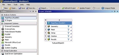
Rename the project to TurbulentPipeLES. We will work through each step from top down to obtain the solution to the problem.
Analysis Type
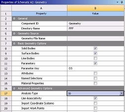
As noted earlier, the computational domain for this simulation will be a full 3-dimensional pipe. In the Project Schematic of the Workbench window, right click on Geometry and select Properties. The properties menu will then appear to the right of the Workbench window. Under Advance Geometry Options, make sure that the Analysis Type is 3D as shown in the image below.
Launch Design Modeler
In the Project Schematic, double click on Geometry to start preparing the geometry.
At this point, a new window, ANSYS Design Modeler will be opened. You will be asked to select desired length unit. Use the default meter unit and click OK.
Creating Cylinder
From the Create menu, choose Primitives and then Cylinder.
Create> Primitives> Cylinder
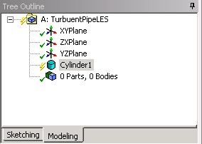
You should see Cylinder1 in Tree Outline as shown in figure below.
Now we have to define the dimensions for the cylinder according to the problem specifications. Let us assume that the axis of the cylinder is in x-direction.
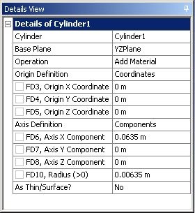
In the Details View table, change Base Plane to YZPlane, Axis X Component to 0.0635 m and Radius (>0) to 0.00635m. Click Generate, this will create a cylinder with YZ plane as the base plane and X-axis as the axis of the cylinder. The cylinder has a diameter of 0.0127 m and is 0.0635 m long. Inputs in the Details View table are shown below.
. 
At this point, you can close the Design Modeler and go back to Workbench Project Page. Save your work thus far in the Workbench Project Page.