 Sign-up for free online course on ANSYS simulations!
Unable to render {include} The included page could not be found.
Unable to render {include} The included page could not be found.
Geometry
2D Analysis Type
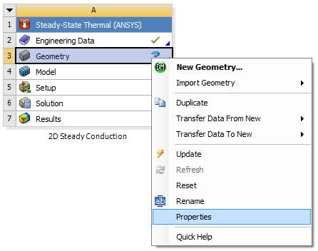
The default Analysis Type is 3D, which must be changed, considering the problem at hand is 2D. This tells ANSYS to use the 2D version of the heat equation as the governing equation in our boundary value problem. In order to make this change first (Right Click) Geometry > Properties, as shown below.

Then set Analysis Type to 2D as shown in the following image.

Launch Design Modeler
In the geometry step, we specify the domain for our boundary value problem which is a rectangle. We'll do this in DesignModeler, the geometry engine in ANSYS Workbench. DesignModeler lets you create a geometry from scratch or import it from a CAD package. We'll do the former for our simple geometry. In order to start DesignModeler (Double Click) Geometry,  . Twiddle your thumbs for a bit. After DesignModeler opens, select meter as the desired length unit.
Proper Orientation
The sketching will be done in the XY plane, so (Click) XY Plane,  , then click on the face plane button,
  .
.
Sketching
In this section a rectangle will be sketched on the XY plane with one corner at the origin. First click on the Sketching tab,  , then click on the Rectangle button,
  . Next,move the mouse over the origin until a "P" appears and click once, then move the cursor somewhere else in the first quadrant and click again. The "P" indicates that the cursor is coincident with a point (in our case, the origin).

Dimensioning
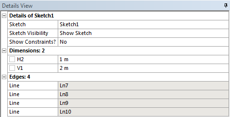
The dimensions of the rectangle will now be specified. First, click on the Dimensions tab,  . Next, click on the left vertical line of your rectangle, move the mouse to the left, then click again. This will create a label for this edge's dimension. We'll specify the actual value of the dimension a little later. Similarly, click on the top horizontal line of your rectangle, move the mouse up and click again. Your screen should now look similar to the image below.

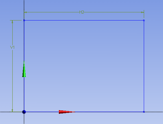
Next, set V1 to 2 and set H2 to 1 as shown below.

Surface Body Creation
In ANSYS, you apply boundary conditions to a "body", not to a sketch. So we need to turn our sketch into a "body". In this case, the "body" is a 2D surface which ANSYS, somewhat awkwardly, calls a "surface body". To create a surface from our sketch, click on the Modeling tab,  . Next, (Click)Concept > Surface From Sketches, as shown below.

Then, Expand XY Plane and click on Sketch 1, as shown below.

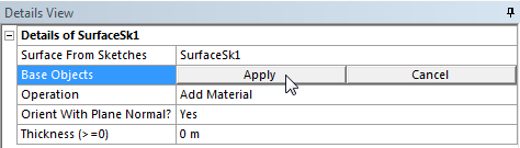
Then (click) Apply under "Details of SurfaceSk1" as shown below.

Now ANSYS knows which sketch to use to create the surface. Lastly, (click) Generate,
 , in order to create the surface body. At this point the rectangle should have become filled in as shown in the following image.

Close DesignModeler and Save
At this point you can close DesignModeler. Then, save the project in the Project Schematic window.
Go to Step 3: Mesh