 Sign-up for free online course on ANSYS simulations!
Unable to render {include} The included page could not be found.
Unable to render {include} The included page could not be found.
Initial Solution
To view the initial solution, select Results from the main project window. The default units in Workbench are Metric, so go to the top menu bar, select Units and change from Metric to U.S.Customary (in).We will begin by viewing the total deformation of the plate. Select Total Deformation from the Solution tree in the Project Outline window on the left.
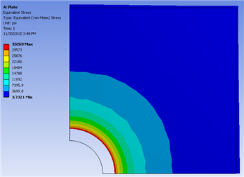
The following images display the results for the initial case in which the radius of the hole is 2 inches.
Total Deformation
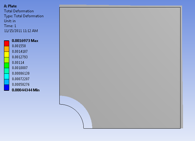

Let's compare the deformed shape of the plate to what we expect from the applied boundary conditions. First, let's look at the radius of the hole. The radius of the hole has uniformly increased, which is consistent with the applied boundary condition of uniform pressure at the radius. Next, let's examine the left and bottom edges of the plate. Motion along these two edges has been parallel to these edges, which agrees with the applied symmetry condition. Finally, let's look at the top and right edges. We can see that both have deformed away from the hole, and the deformation is smallest at the top right corner, which agree with our expectations.
Equivalent Stress

Go to Step 3: Input & Output Parameters