 Sign-up for free online course on ANSYS simulations!
Author: Sebastien Lachance-Barrett, Cornell University
Problem Specification
1. Pre-Analysis & Start-Up
2. Initial Solution
3. Input & Output Parameters
4. Design of Experiments
5. Response Surface
6. Optimization
7. Verification & Validation
Exercises
Comments
Initial Solution
To view the initial solution, select  from the main project window. The default units in Mechanical are Metric, so go to the top menu bar, select Units and change from Metric to U.S.Customary (in). If you do not do this now then you will likely have to start over so please change your units at this point. We will begin by viewing the total deformation of the plate. Select Total Deformation from the Solution tree in the Project Outline window on the left.

The following images display the results for the initial case in which the radius of the hole is 2 inches.
Total Deformation


Let's compare the deformed shape of the plate to what we expect from the applied boundary conditions. First, let's look at the radius of the hole. The radius of the hole has uniformly increased, which is consistent with the applied boundary condition of uniform pressure at the radius. Next, let's examine the left and bottom edges of the plate. Motion along these two edges has been parallel to these edges, which agrees with the applied symmetry condition. Finally, let's look at the top and right edges. We can see that both have deformed away from the hole, and the deformation is smallest at the top right corner, which agree with our expectations.
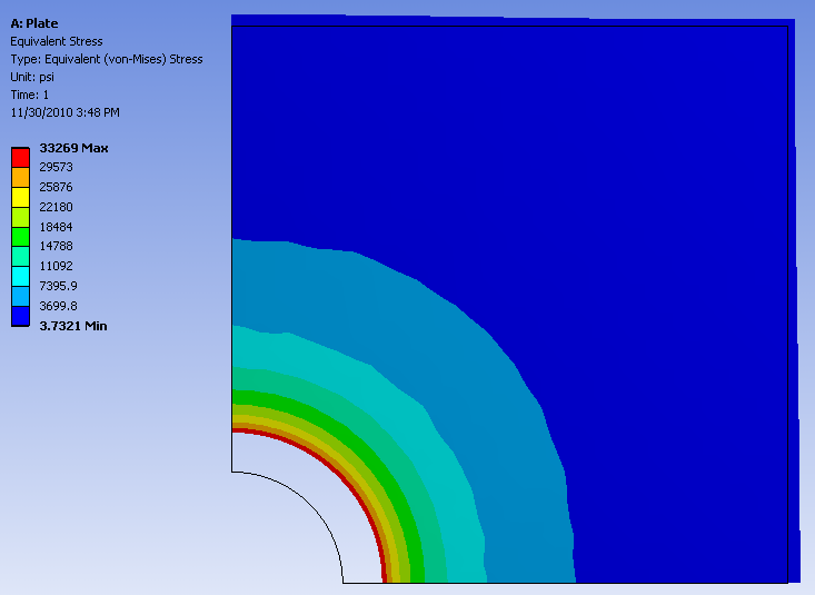
Equivalent Stress
Next, let's view the Equivalent Stress values calculated by ANSYS. Select Equivalent (von-Mises) Stress from the tree in the left panel. We would now like to view the stresses as colored contours. Select the Contours from the top toolbar and choose Contour Bands.

The following image should now appear, representing the contour bands representation of the von Mises Stress.

Now let's do a quick mesh convergence study to make sure that our solution is good enough. Remember that more elements in a mesh might give more accurate results but can significantly increase the computational time. So we want to refine our mesh (have more elements) until the solution changes so little that we can deem it to be accurate enough for our purposes. In different words, we will have ANSYS refine the mesh until the change in a chosen criteria is less than a specified percent difference. In this example, the criteria we will examine is the maximum value of the von Mises Stress. From the tree on the left, right-click Equivalent (von Mises) Stress > Insert > Convergence. Set the Allowable Change to 5%, as seen below.

Next, click Solve in the top toolbar. It turns out that ANSYS only needs one iteration to reach the Allowable Change. After one iteration, we see that there is a change of around 0.10% in the maximum von Mises Stress in the plate. From this, we can conclude that our solution is mesh converged.
To see the final mesh that ANSYS has created during the "convergence" process, select any result and then select "Show Elements" as shown in the figure below.

Next, right click on Convergence in the tree on the left and choose Delete. This is done to speed up the optimization process, which we will now move onto.