 Sign-up for free online course on ANSYS simulations!
Unable to render {include} The included page could not be found.
Under Construction
This page is under construction. Please return later for updates
Geometry
Set Up
First, we need to specify that the geometry is 2-dimensional. Right click the Geometry box  and select Properties. This will open the Properties of Schematic A2: Geometry Window. Under Advance Geometry Options change Analysis Type from 3D to 2D.

After the analysis type has been set, we are ready to launch Design Modeler, the design tool in ANSYS. Open Design Modeler by double clicking the geometry box . After launching the Design Modeler, you will be prompted to choose a standard unit of measurement. Select Meter as the standard unit, and click OK.
Sketching
We want to sketch on the XY plane. To look at the XY plane, click the positive Z-Axis on the compass in the Graphics window.

To begin sketching, click on the Sketching tab in the Tree Outline window. To draw our domain, we will use the Rectangle tool. Click on  in the Sketching Toolboxes window. In the graphics window, draw the rectangle by first clicking on the origin (make sure the P icon is showing, meaning you are in fact selecting the point), then select a point in the 1st quadrant.

Because there are two sections to our domain, a heated section and an isothermal section, we will need to split the upper surface of our domain. To split the line, select the Modify tab in the Sketching Toolboxes window, and select  . Next, click any point along the upper surface of the rectangle. This will split the line into 2 segments.

Dimensioning
The next step in creating the domain will be adding dimensions. In the Sketching Toolboxes window, select Dimensions > General. First, click the left segment of the upper surface of the rectangle, then click off off of the geometry to place the dimension. Repeat this process for the right segment of the upper surface of the rectangle, then the left surface of the rectangle.

We can set the dimension in the Details View window. In the Details View window, change H1 to 5.76, H2 to 2.88, and V3 to .06.
Surface from Sketches
To finish the domain, we must create a surface. To accomplish this, click Concept > Surfaces From Sketches in the menu bar. Next, click any edge on the sketch in the Graphics window. In the Details View window, select Base Objects > Apply. Next, click Generate  to create the surface. The geometry of the domain, if you have followed the tutorial successfully, should look like this:

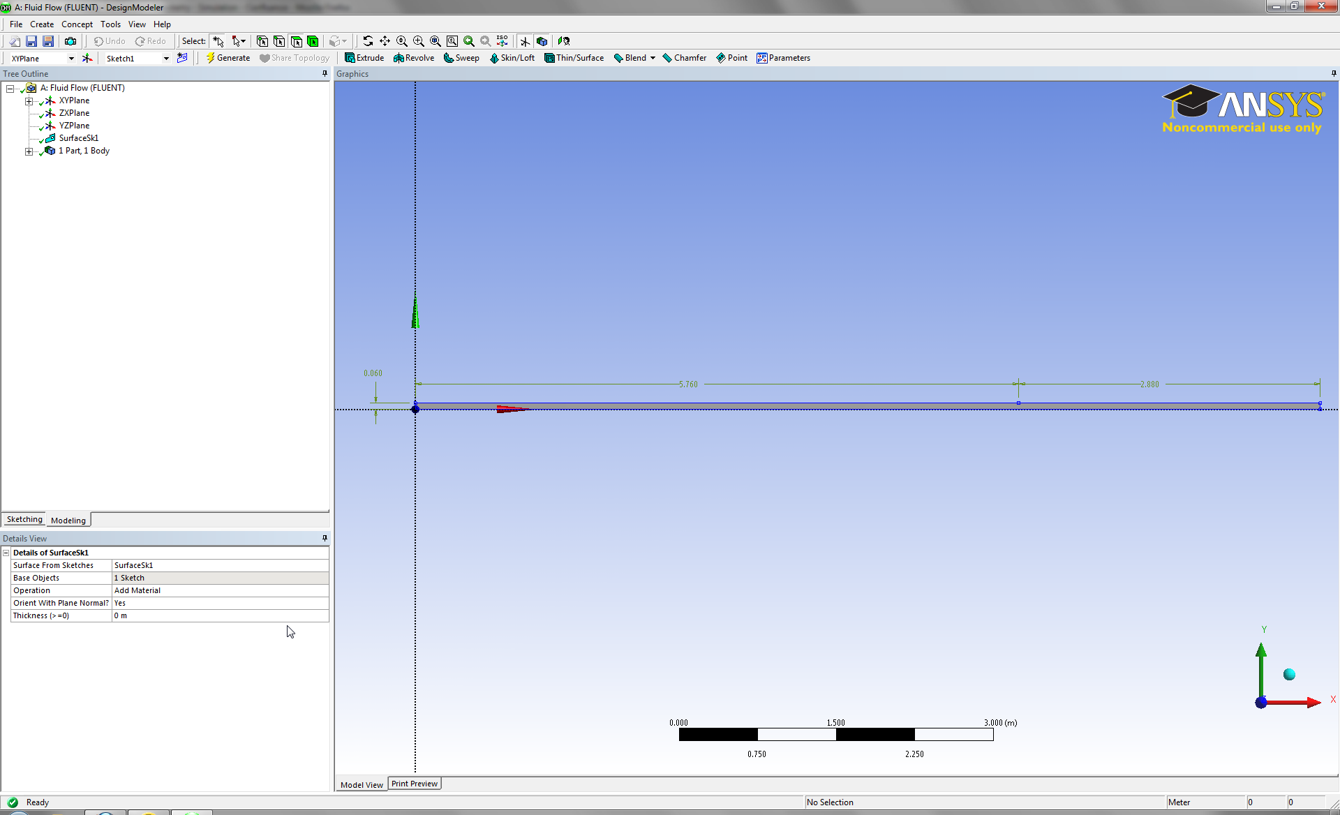
Save the project, and close the design modeler. We are ready to move on.