 Sign-up for free online course on ANSYS simulations!
Unable to render {include} The included page could not be found.
Author: John Singleton, Cornell University
Problem Specification
1. Pre-Analysis & Start-Up
2. Geometry
3. Mesh
4. Setup (Physics)
5. Solution
6. Results
7. Verification and Validation
Exercises
2. Geometry
2D Analysis Type
The default analysis type is 3D, so that must be changed, considering the problem at hand is two dimensional. In order to make this change first (Right Click) Geometry > Properties, as shown below.

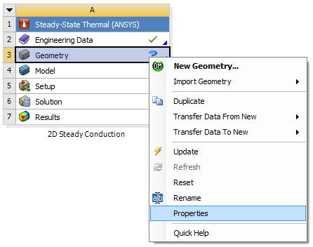
Then set Analysis Type to 2D as shown in the following image.

Launch Design Modeler
In order to launch the Design Modeler
2D Analysis Type
The default analysis type is 3D, so that must be changed. In order to make this change (Right Click) Geometry > Properties then change Analysis Type to 2D.
Launch Design Modeler
In order to start the Design Modeler (Double Click) Geometry. After the Design Modeler opens, select inch as the desired length unit.
Proper Orientation
The sketching will be done in the XY plane, so (Click) XY Plane, then click on the face plane button, .
Line Sketching
The given problem is axisymmetric. That is, in terms of position, the results will only vary in the radial direction. Thus, the problem will be modeled with a rectangle in the first quadrant of the XY plane. First click on the Sketching Tab,  , then click on the Rectangle button,
  . Next, draw a rectangle in the first quadrant of the XY plane. Your screen should look comparable to the image below.
Dimensioning
The dimensions of the rectangle will now be inputted into ANSYS. Dimension the rectangle as shown in the image below.

Now, specify the dimensions as shown in the image below.

Note, that the given length of the pipe is 10 feet: however, here the height has been specified to 3 inches. The height is arbitrary because the results only vary radially.
Surface Creation
Here, the rectangle will be turned into a surface. To do so (Click)Concept > Surface From Sketches. Next, highlight all four edges of the rectangle and select Apply in the "Details of SurfaceSK1" table. Now, click the generate button, , in order to create the surface.
At this point save the project and then exit the Design Modeler.