Nonlinear Chemical Dose Controller
Abstract
Unknown macro: {float}
Unable to render embedded object: File (Non-linear CDC Design.jpg) not found.
Figure 1: Nonlinear CD Design
The nonlinear chemical doser (CD) is designed for turbulent chemical does flow rates. The linear CD requires that the chemical flow in the dosing tube be laminar. The linear CD uses the relationship between laminar flow and major losses in the doser tube to maintain a constant chemical dose with varying plant flow rates. However, when the flow in the dosing tube is turbulent, the linear relationship no longer exists. In this case, a nonlinear CD, one that uses minor losses to control flow rates, can be used to maintain a constant chemical dose with the varying plant flow rates. By using an orifice to control chemical flow, the CD will have the same nonlinear response to increasing flow as the plant flow rate which is controlled by a rectangular orifice. A float in the grit chamber controls the height of a lever arm. The dosing orifice is located at the opposite end of the lever arm. As plant flow rates increase, the float rises, and the dosing orifice falls making more head available to power chemical flow. As the flow rate decreases so does the available head and the chemical flow rate slows down.
Add a description of how the plant flow measurement device must be matched to the CD. Include the equations that show that the relationship between flow and height must have the same power relationship.
The figure shows an orifice that would be difficult to fabricate. Come up with a simpler design that can be fabricated at the construction site.
Could you provide clearer drawings of your design?
The advantage to designing a nonlinear CD is that higher chemical flow rates can be used. With an alum stock solution of 500 grams per liter the linear flow controller can deliver a maximum chemical dose of 90 mg/L to plants with flow rates as high as 2000 L/min. In larger water treatment plants higher chemical flow rates are necessary to dose alum and chlorine. The limit of the linear flow control module is 400 ml/min. This maximum flow has been adequate for La 34, Ojojona, Tamara, and Four communities given their flow rates. It was necessary to use two flow controllers at Marcala to obtain a high enough alum dose. As the demand for larger AguaClara plants grows, larger chemical dose flow rates will be required. Furthermore, at high chemical flow rates, the head loss through the flow control module orifice requires that the chemical stock tank be elevated to an unreasonable height.
The link to the flow controller doesn't discuss the orifice issue. Define the head loss problem clearly. Which orifice causes the problem and why can't that problem be solved? Are you sure this is a constraint?
Methods
The nonlinear doser uses a dosing orifice (minor losses) instead of a dosing tube (major losses) to control the relationship between changing plant flow rates and chemical dose. The flow rate through the orifice is related to the available head by the equation:
Unknown macro: {latex}
$$Q_c = K h^
Unknown macro: {n_c }
$$
where
- Q c is the chemical flow rate
- K is the minor loss coefficient for an orifice
- h is the available head
- n c is an unknown power
The entrance to the rapid mix tank is a rectangular orifice. The relationship between flowrate and head is governed by the equation:
Unknown macro: {latex}
$$Q_p = K h^
Unknown macro: {n_p }
$$
where
- Q c is the chemical flow rate
- n c is an unknown power
The chemical dose to the plant can be determined by a simple mass balance:
Unknown macro: {latex}
$$C_p = {{C_c Q_c } \over {Q_p }}$$
where
- C c is the chemical stock concentration
- C p is the chemical dose
The CD uses a lever arm to relate head in the rectangular plant entrance orifice to head in the dosing orifice. This means that the available head for the dosing orifice is the same as the head controlling the plant flow rate. The increase in head links the chemical flow rate to the plant flow rate and the chemical dose will be constant as long as n p = n c.
A lever arm similar to the linear CD lever arm will be used to relate plant flow rate to chemical flow rate. A larger dosing tube is required to minimize major losses. This tube must be flexible to accommodate lever arm motion. Flow will be channeled through the dose control orifice into a channel. This channel will deposit chemical flow into the same position in the rapid mixer regardless of the corresponding dosing location on the lever arm.
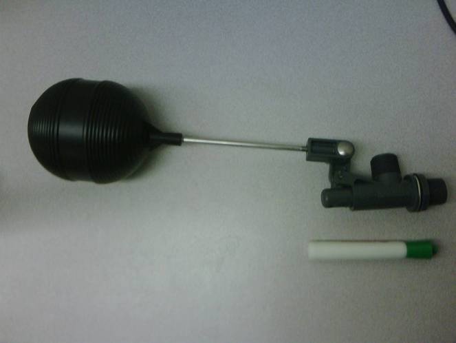
To reduce head loss through the flow control module orifice, a new flow controller is being used in the design. The module being used is a PT 75 LS![]() Kerick Valve. When choosing what size float valve to use, the constraints are the allowable flow rate through the valve, the head loss through the valve, and the size of the valve. In this case, a valve was needed that would allow a flow rate of least 15 gal/min, the maximum alum flow rate needed going into rapid mix. To minimize head loss, a 3/4 inch orifice was chosen. The flow controller will be mounted in a tub, so it cannot be too large. The float valve that fit all of these constraints was the PT 75 LS.
Kerick Valve. When choosing what size float valve to use, the constraints are the allowable flow rate through the valve, the head loss through the valve, and the size of the valve. In this case, a valve was needed that would allow a flow rate of least 15 gal/min, the maximum alum flow rate needed going into rapid mix. To minimize head loss, a 3/4 inch orifice was chosen. The flow controller will be mounted in a tub, so it cannot be too large. The float valve that fit all of these constraints was the PT 75 LS.
- Document the design of the constant head tank float valve.
- Distinguish clearly between the three orifices that are used (plant flow leaving the entrance tank, chemical flow leaving the dosing tube, and chemical panel valve).
- Add a detailed description of the design algorithms that you created for the plant flow measurement orifice, the chemical flow orifice, the float valve, and the dosing tube.
- Give the expected range of applicability of this design.
- Describe the design process for the CD lever and float.
I would suggest editing the [Gracias entrance tank design] page first. The comments there urge you to write a more generic overview of entrance tank design, and you can document the rapid mix design there and then put a link on this page to that one. I don't think it would make sense to document the rapid mix design here, but you need to make sure there is a mention of it and a link to the design work. -Nicole