Nonlinear Chemical Dose Controller Fall 2008-Summer 2009
Abstract

The nonlinear chemical dose controller (CDC) is designed for turbulent chemical dose flow rates to be used in conjunction with the Rapid Mix Chamber Design in contrast to the linear CDC which requires that the chemical flow in the dosing tube be laminar. The linear CDC uses the relationship between laminar flow and major losses in the doser tube to maintain a constant chemical dose with varying plant flow rates. However, when the flow in the dosing tube is turbulent, the linear relationship no longer exists. In this case, a nonlinear CDC, one that uses a combination of major and minor losses to control flow rates, can be used to maintain a constant chemical dose with the varying plant flow rates. By using an orifice to control chemical flow, the CDC will have the same nonlinear response to increasing flow as the plant flow rate which is controlled by a rectangular orifice. A float in the entrance tank controls the height of a lever arm. The dosing orifice is located at the opposite end of the lever arm. As plant flow rates increase, the float rises, and the dosing orifice falls making more head available to power chemical flow. As the flow rate decreases so does the available head and the chemical flow rate slows down. The lever arm has holes drilled into the top of it so that the dosing orifice may be inserted into one of these holes to adjust dosage for changes in turbidity. Since the dosing orifice flows directly into the lever arm, the alum will always be dispersed into the same spot, no matter the dose.
The advantage to designing a nonlinear CDC is that higher chemical flow rates can be used. With an alum stock solution of 500 g/L the linear flow controller can deliver a maximum chemical dose of 90 mg/L to plants with flow rates as high as 2000 L/min. In larger water treatment plants higher chemical flow rates are necessary to dose alum and chlorine. A flow controller with a higher capacity than the linear CDC flow controller is necessary for the nonlinear CDC. Head loss through the float valve orifice limits the Flow Controller to chemical flows less than 400 mL/min. Otherwise; the chemical stock tank needs to be placed excessively far above the flow controller float valve. This maximum chemical flow is adequate for La 34, Ojojona, Tamara, and Cuatro Comunidades given their flow rates. Two flow controllers working in parallel are used to achieve the necessary alum dose at Marcala. As the demand for larger AguaClara plants grows, larger chemical flow rates will be required.
Theory
The nonlinear doser uses a dosing orifice (minor losses) instead of a dosing tube (major losses) to control the relationship between changing plant flow rates and chemical dose. The flow rate through the CDC is related to the available head by the equation:
Unable to find DVI conversion log file.where
- Unable to find DVI conversion log file. is the chemical flow rate
- Unable to find DVI conversion log file. is the orifice coefficient
- h is the available head
The entrance to the rapid mix tank is a rectangular orifice. The relationship between flow rate and head is governed by the equation:
Unable to find DVI conversion log file.where
- Unable to find DVI conversion log file. is the plant flow rate
- Unable to find DVI conversion log file. is the height of water above the entrance tank orfice
The chemical dose to the plant can be determined by a simple mass balance:
Unable to find DVI conversion log file.where
- C c is the chemical stock concentration
- C p is the chemical dose
The CDC uses a lever arm to relate head above the centerline of the rectangular plant entrance orifice to head in the dosing orifice. This means that the available head for the dosing orifice is the same as the head controlling the plant flow rate. The increase in head links the chemical flow rate to the plant flow rate and the chemical dose will be constant as plant flow varies as long as the exponent of the head is the same for both the plant flow and the chemical flow.
The dosing tube must be designed to minimize major losses so that the major losses that deviate from the Unable to find DVI conversion log file. relationship do not cause excessive errors. The deviation from Unable to find DVI conversion log file. is especially significant when the flow through the dosing tube becomes laminar. The dosing tube must be flexible to accommodate the lever arm motion and dose adjustment. The flow conduit used to transport the chemical flow from the orifice to the place where it is mixed with the plant flow must still be designed. The flow conduit must be designed such that the pressure is atmospheric at the exit of the dose control orifice.
Methods
Flexible Dosing Tube
The dosing tube diameter is based on the minimum available diameter that will have a head loss less than the given fraction of the maximum CDC head loss under conditions of the maximum chemical flow rate.
Dosing Orifice
The dosing orifice is designed to produce the difference in head loss between the maximum CDC head loss and the actual head loss in the flexible dosing tube:
Unable to find DVI conversion log file.where
- h l the difference in head loss between the maximum CDC head loss and the actual head loss in the flexible dosing tube
- K DoseOrifice is the required minor loss coefficient through the orifice
- V DoseTube is the velocity in the dosing tube
This head loss is equal to head loss in the vena contracta. Head loss in the vena contracta is modeled by the equation:
Unable to find DVI conversion log file.where
- h l is the head loss
- Unable to find DVI conversion log file. is the minor loss coefficient from an exit to the atmosphere
- V VenaContracta is the velocity in the orifice vena contracta
Unable to find DVI conversion log file. is equal to one. The flow rate through the dosing tube is known and velocities in the vena contracta can be found using mass conservation:
Unable to find DVI conversion log file.where
Unable to find DVI conversion log file. is the orifice vena contracta coefficient equal to 0.63. Using the three equations above a relationship for the velocities can be found:
The chemical dose flow rate is not exactly proportional to the plant flow rate due to different exponential relationships between flow and head loss for the major losses. These differences arise from two sources. The most significant difference occurs when the flow in the dosing tube is laminar and thus the flow rate is proportional to the major head loss rather than to the square root of the head loss. The other source of error occurs for transitional flow where the friction factor decreases with increasing Reynolds number.
Unknown macro: {float}

Figure 2: Dosing error from the nonlinear CDC for two maximum flow rates and for two chemical doses. The conditions were: 1 m long dosing tube, CDC head loss of 50 cm, major losses constrained to less than 10% of total head loss, stock concentration of 120 g/L, maximum chemical dose of 60 mg/L, and minimum plant flow that could be measured by the plant flow orifice was 20%. The MathCAD file is attached.
The error due to the major loss contribution to the head loss is shown in figure 2. The error is most significant for low chemical flow rates. The error can be reduced by decreasing the major losses, but that requires the use of larger dosing tubes.
The nonlinear relationship between flow and head loss makes it more difficult to accurately control the chemical dose when the dose is low.
Unable to find DVI conversion log file.
For this reason it is recommended that the total head loss range be increased to approximately 50 cm for the nonlinear CDC. For a chemical dose that is 10% of the maximum chemical dose the head required by the dosing tube is 1% of the maximum head loss (0.5 cm). Maintaining a positioning error of less than 0.5 cm may be difficult and would require a large float to minimize errors due to changes in moment caused by the dosing tube. The CDC lever must also be accurately calibrated to minimize errors at low chemical dosing rates. Thus the maximum head loss for the CDC should be at least 50 cm.
Viscosity of Alum

The viscosity of alum is only slightly larger than that of water for concentrations used in stock solutions (Figure 3). At concentrations above 550 g/L the viscosity increases rapidly and thus concentrations above 550 g/L should be avoided when using hydraulic flow control.
Lever Arm and Float
Since the head loss range required to accurately control the chemical dose at low chemical dosages is at least 50 cm, the length of the lever arm must be sufficient to handle that vertical motion.
Refer to LeverArmLength to determine a lever arm length and the maximum angle to use for a given elevation difference
The size of the float can be determined using a moment balance around the pivot of the lever arm. This is to ensure that a change of 20 cm in head in the entrance tank will cause a similar change in the relative height of the float. The float was sized using the same float sizing algorithm used by the linear CDC. For flows between 600 and 25,000 L/min the float diameter ranged between 6 and 16 in.
Flow Control module
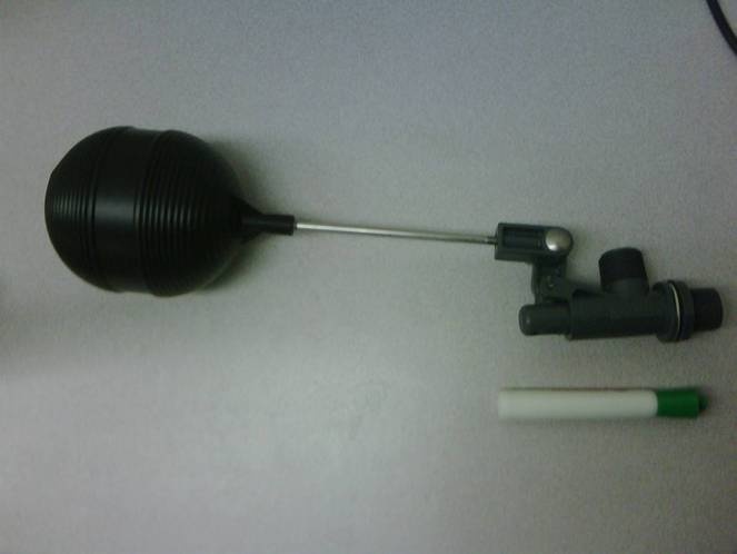
When choosing what size float valve to use, the constraints are the maximum flow rate through the valve, the allowable head loss through the valve, and the size of the valve orifice. The allowable head loss through the valve is kept small to avoid excessively elevated stock tanks for alum and chlorine. Various valve orifices sizes are available. Note that the inlet sizes given (a pipe thread size) are not the orifice dimension.
Functional Range
The functional range is limited by the float valve orifice. The largest float valve manufactured by Kerick Valve has an orifice of 2.54 cm (1 inch). With a head loss of 30 cm the flow rate would be 0.77 L/s and the corresponding plant flow rate could be as high as 6000 L/s.