Nonlinear Chemical Dose Controller
Abstract
Unknown macro: {float}
Unable to render embedded object: File (Non-linear CDC Design Draft F.jpg) not found.
Figure 1: Nonlinear CD Design
The nonlinear chemical doser (CD) is designed for turbulent chemical does flow rates. The previous CD design for a [linear CD] requires that the chemical flow in the dosing tube be is laminar. This The linear CD design uses the relationship between laminar flow and major losses in the doser tube to maintain a constant chemical dose with varying plant flow rates. However, when the flow in the dosing tube is turbulent, the linear relationship no logner longer exists. In this case, a nonlinear CD, one that uses minor losses to control flow rates, is necessary can be used to maintain a constant chemical dose with the varying plant flow rates.
Add a description of how the plant flow measurement device must be matched to the CD. Include the equations that show that the relationship between flow and height must have the same power relationship.
The figure shows an orifice that would be difficult to fabricate. Come up with a simpler design that can be fabricated at the construction site.
Could you provide clearer drawings of your design?
The advantage to designing a nonlinear CD is that higher chemical flow rates can be used. In larger water treatment plants
How large? What is the maximum plant flow rate for the linear flow controller?
It was necessary to use two flow controllers at Marcala.
The link to the flow controller doesn't discuss the orifice issue. Define the head loss problem clearly. Which orifice causes the problem and why can't that problem be solved? Are you sure this is a constraint?
Methods
The nonlinear doser uses a dose control orifice (minor losses) instead of a dosing tube (major losses) to control the relationship between changing plant flow rates and chemical dose. The entrance to the rapid mix tank is also an orifice. Therefore, the relationship the total plant flow rate and the height of water in the entrance tank and the relationship between the chemical flow rate both plant and chemical flow rates are dominantly controlled by an orifice flow. The CD uses a lever arm to increase head in the flow control module when the plant flow rate increase. The increase in head drives links the chemical flow rate to increase with the plant flow rate. The relationship between chemical dose and turbidity is changed manually in the same fashion as for the linear CD.
A lever arm similar to the linear CD lever arm will be used to relate plant flow rate to alum chemical flow rate. A larger dosing tube is required to minimize major losses. This tube must be flexible to accommodate lever arm motion. Flow will be channeled through the dose control orifice into a channel. This channel will deposit chemical flow into the appropriate
What is the appropriate location?
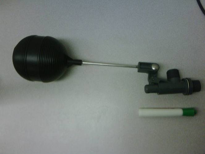
To reduce head loss through the flow control module orifice, a new flow controller is being used in the design. The module being used is a PT 75 LS![]() Kerick Valve. This valve was chosen to minimize flow control module size and maximize orifice area. The flow controller will be housed mounted in a square tub.
Kerick Valve. This valve was chosen to minimize flow control module size and maximize orifice area. The flow controller will be housed mounted in a square tub.
- Document the design of the constant head tank float valve.
- Distinguish clearly between the three orifices that are used (plant flow leaving the entrance tank, chemical flow leaving the dosing tube, and chemical panel valve).
- Is it important that the constant head tank be square?
- Add a detailed description of the design algorithms that you created for the plant flow measurement orifice, the chemical flow orifice, the float valve, and the dosing tube.
- Give the expected range of applicability of this design.
- Describe the design process for the CD lever and float.
- Document the rapid mix design. The rapid mix design is very important for the larger plants and deserves a detailed description of how it is designed.