Nonlinear Chemical Dose Controller
Abstract
The nonlinear chemical doser (CD) was designed to accommodate turbulent flow in the chemical doser tubing. The previous chemical doser design, the [Linear Chemical Doser], requires that the alum flow be laminar. This design uses the relationship between laminar flow and major losses in the doser tube to maintain a constant chemical dose with varying plant flow rates. However, when the flow in the dosing tube is turbulent, major losses can no longer create this linear relationship. In this case, a nonlinear CD, that uses minor losses to control flow rates is necessary to maintain a constant chemical dose with varying flow rates.
The advantage to designing a nonlinear CD is that higher chemical flow rates can be used. This is necessary in larger water treatment plants where larger chemical flow rates are necessary to dose alum and chlorine. The limit of the current flow control module is 400 ml/min. This has been adequate for the plants currently in operation (La 34, Ojojona, Tamara, Marcala and Four communities) given their low flow rate capacity. As the demand for larger AguaClara plants grows, larger chemical dose flow rates will be required. Furthermore, headloss through the flow control module orifice increases as chemical flow rate increases and as a result, requires the chemical stock tank to be elevated to an unreasonable height.
Unable to render embedded object: File (Non-linear CDC Design Draft F.jpg) not found.
Methods
The non-linear doser uses a dose control orifice (minor losses) instead of a dosing tube (major losses) to control the relationship between changing plant flow rates and chemical dose. The entrance to the rapid mix tank is also an orifice; therefore, the plant and chemical flows vary in direct proportion to each other. The relationship between chemical dose and turbidity will be changed manually as it is done with the linear CD.
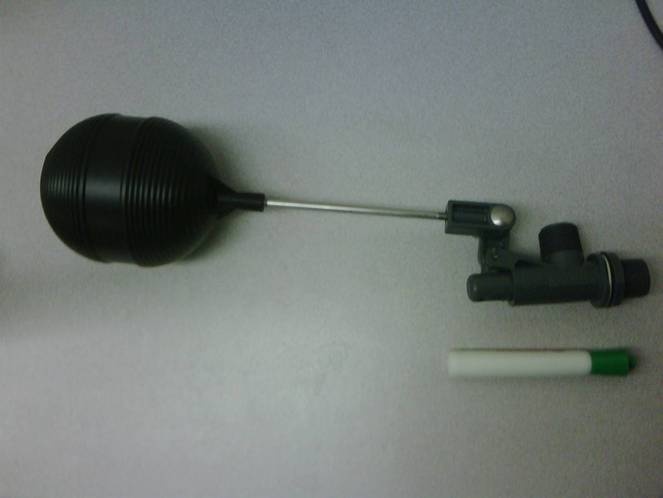
To reduce head loss through the flow control module orifice, a new flow controller is being used in the design. The module being used is a PT 75 LS![]() Kerick Valve. This valve was chosen to minimize flow control module size and maximize orifice area. The flow controller will housed in a square tub.
Kerick Valve. This valve was chosen to minimize flow control module size and maximize orifice area. The flow controller will housed in a square tub.
A lever arm similar to the design for the linear CD will be used to relate plant flow rate to alum flow rate. A larger dosing tube is required to minimize major losses. This tube must be flexible to accomodate lever arm motion. Flow will be channelled through the dose control orifice into a channel. This channel will deposit chemical flow in to the appropriate location in the entrance tank regardless of the corresponding dosing location on the lever arm.