 Sign-up for free online course on ANSYS simulations!
Step 2: Mesh Geometry in GAMBIT
Mesh Edges
Before we mesh the face, we should mesh the edges to better define our mesh.
Following figure shows the edges with different mesh properties.
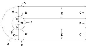
(Click picture for larger image)
Label |
Edge Mesh Properties |
A |
Interval Count: 36, Double First Length: 0.4667 |
B |
Interval Count: 36, Double First Length: 0.1867 |
C |
Interval Count: 30, First Length: 0.129 |
D |
Interval Count: 18 |
E |
Interval Count: 90, First Length: 0.1 |
F |
Interval Count: 36 |
G |
Interval Count: 72 |
H |
Interval Count: 30 |
I |
Interval Count: 36, Double First Length: 0.04667 |
Operation Toolpad > Mesh Command Button ![]() > Edge Command Button
> Edge Command Button ![]() > Mesh Edges
> Mesh Edges ![]()
Mesh edge A through I according to the properties shown on the table.
After we have all the edge meshes, we can mesh the faces:
Operation Toolpad > Mesh Command Button ![]() > Face Command Button
> Face Command Button ![]() > Mesh Faces
> Mesh Faces ![]()
Select the face one by one. The face will change color. You can use the defaults of Quad (i.e. quadrilaterals) and Map. Click Apply.
The meshed face should look as follows:
(Click picture for larger image)

Next mesh face face2 in a similar fashion.
The resultant mesh should look as follows:
(Click picture for larger image)

Note that for each mesh face, we only define 2 mesh edges. Gambit will automatically define the other two mesh edge for face mesh creation. Manual mesh of all edges can be done if more control of the mesh is required. Please refer to the index of the GAMBIT User Guide and look under Edge>Meshing for explanation on other type of meshing parameters.
Go to Step 3: Specify Boundary Types in GAMBIT