 Sign-up for free online course on ANSYS simulations!
Author: Rajesh Bhaskaran & Yong Sheng Khoo, Cornell University
Problem Specification
1. Create Geometry in GAMBIT
2. Mesh Geometry in GAMBIT
3. Specify Boundary Types in GAMBIT
4. Set Up Problem in FLUENT
5. Solve
6. Analyze Results
7. Refine Mesh
Problem 1
Problem 2
Step 2: Mesh Geometry in GAMBIT
Mesh Edges
Before we mesh the faces, we should mesh the edges so that we can better define the mesh.
Following figure shows the edges with different mesh properties.

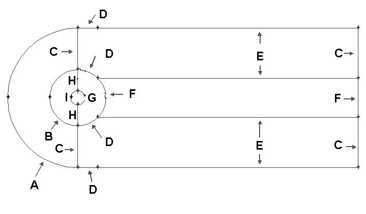
Label |
Edge Mesh Properties |
A |
Interval Count: 36, Double First Length: 0.5 |
B |
Interval Count: 36, Double First Length: 0.2 |
C |
Interval Count: 30, First Length: 0.1 |
D |
Interval Count: 18 |
E |
Interval Count: 90, First Length: 0.1 |
F |
Interval Count: 36 |
G |
Interval Count: 72 |
H |
Interval Count: 30 |
I |
Interval Count: 36, Double First Length: 0.05 |
Operation Toolpad > Mesh Command Button ![]() > Edge Command Button
> Edge Command Button ![]() > Mesh Edges
> Mesh Edges ![]()
Mesh edge 'A' through 'I' according to the properties shown on the table.
After we have all the edge meshes, we can mesh the faces:
Operation Toolpad > Mesh Command Button ![]() > Face Command Button
> Face Command Button ![]() > Mesh Faces
> Mesh Faces ![]()
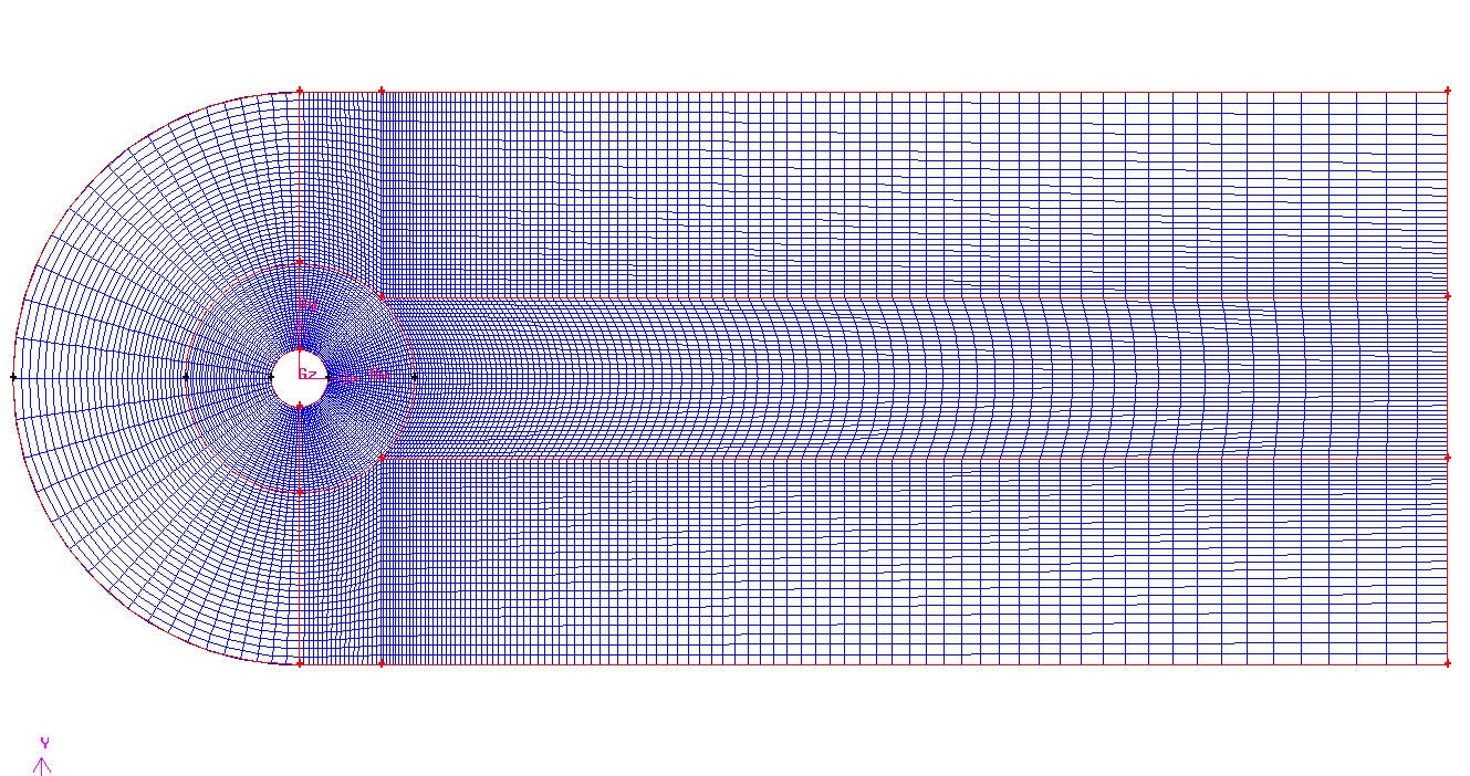
Select the face one by one. You can use the defaults of Quad (i.e. quadrilaterals) and Map. Click Apply.
The meshed face should look as follows:

Go to Step 3: Specify Boundary Types in GAMBIT