 Sign-up for free online course on ANSYS simulations!
| Panel |
|---|
| Wiki Markup |
| {alias:crank}
{panel}
Author: Rajesh Bhaskaran, Cornell University {color:#ff0000}{*}Problem Specification{*}{color} [1.University Problem Specification |
| Note | ||
|---|---|---|
| ||
The following ANSYS tutorial is under construction. |
Problem Specification
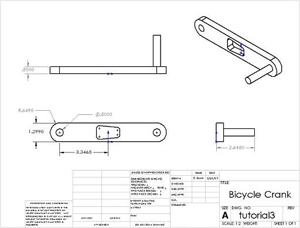
A preeminent bicycle company is disappointed with the negative feedback they have received on their latest model, and they have pinpointed the problem to an outdated bicycle crank design that they assumed would still withstand typical loads. To protect their reputation, they have outsourced the task of analyzing the crank to you, providing you with the geometry of the bicycle crank and attached pedal shaft shown below. The dimensions are given in inches. The material they selected has an Young's modulus E=2.8x10⁷ psi and Poisson ratio ν=0.3.
| newwindow | ||||
|---|---|---|---|---|
| ||||
results|ANSYS - Crank Step 9] {panel} h2. Problem Specification h4. A preeminent bicycle company is disappointed with the negative feedback they have received on their latest model, and they have pinpointed the problem to an outdated bicycle crank design that they assumed would still withstand typical loads. To protect their reputation, they have outsourced the task of analyzing the crank to you, providing you with the geometry of the bicycle crank and attached pedal shaft shown below. The dimensions are given in inches. The material they selected has an Young's modulus _E_=2.8x10{^}7^ psi and Poisson ratio _ν_=0.3. !crank.jpg! {newwindow:Higher Resolution Image}https://confluence.cornell.edu/download/attachments/82384572/crankDiagram.jpg?version=1{newwindow} |
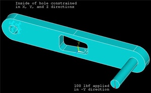
Using
...
ANSYS,
...
determine
...
the
...
mechanical
...
response
...
due
...
to
...
a
...
load
...
of
...
100
...
lbf
...
applied
...
vertically
...
downward
...
at
...
the
...
end
...
of
...
the
...
pedal
...
shaft
...
as
...
shown
...
in
...
the
...
figure
...
below.
...
Assume
...
that
...
the
...
crank
...
is
...
attached
...
rigidly
...
to
...
a
...
fixed
...
shaft
...
fitted
...
into
...
the
...
hole
...
near
...
the
...
left
...
end
...
of
...
the
...
crank.
...
This
...
means
...
you
...
can
...
constrain
...
the
...
surface
...
of
...
the
...
left
...
hole
...
in
...
X
...
,
...
Y
...
and
...
Z
...
directions
...
as
...
indicated
...
below.
...
Calculate the deflection,
...
strain
...
and
...
stress
...
distributions
...
in
...
the
...
crank/pedal
...
shaft
...
combination
...
for
...
this
...
loading
...
condition.
...
Use
...
the
...
ANSYS
...
results
...
to
...
evaluate
...
the
...
degree
...
of
...
stress
...
concentration
...
in
...
the
...
vicinity
...
of
...
the
...
cut-out
...
in
...
the
...
crank
...
geometry.
...
...
...
...
...
...
...
...
...