| Panel |
|---|
| Wiki Markup |
|---|
| {alias:crank}
{panel}
Author: Rajesh Bhaskaran, Cornell University
{color:#ff0000}{*}Problem Specification{*}{color}
[1. University Problem Specification
1. Start-up and preliminary set-up |ANSYS - Crank Step 1]
[
2.
Specify element type and constants|ANSYS - Crank Step 2]
[constants
3. Specify material properties|ANSYS - Crank Step 3]
[properties
4. Specify geometry|ANSYS - Crank Step 4]
[geometry
5. Mesh geometry|ANSYS - Crank Step 5]
[geometry
6. Specify boundary conditions|ANSYS - Crank Step 6]
[conditions
7. Solve \!|ANSYS - Crank Step 7]
[!
8. Postprocess the results|ANSYS - Crank Step 8]
[results
9. Validate the results|ANSYS - Crank Step 9]
{panel}
h2. Problem Specification
h4.
A preeminent bicycle company is disappointed with the negative feedback they have received on their latest model, and they have pinpointed the problem to an outdated bicycle crank design that they assumed would still withstand typical loads. To protect their reputation, they have outsourced the task of analyzing the crank to you, providing you with the geometry of the bicycle crank and attached pedal shaft shown below. The dimensions are given in inches. The material they selected has an Young's modulus _E_=2.8x10{^}7^ psi and Poisson ratio _ν_=0.3.
!crank.jpg!
[(click here and maximize browser for high-resolution view|^crankDiagram.jpg])
Using ANSYS, determine the mechanical response due to a load of 100 lbf applied vertically downward at the end of the pedal shaft as shown in the figure below. Assume that the crank is attached rigidly to a fixed shaft fitted into the hole near the left end of the crank. This means you can constrain the surface of the left hole in _X_, _Y_ and _Z_ directions as indicated below.
!crank2.jpg!
Calculate the deflection, strain and stress distributions in the crank/pedal shaft combination for this loading condition. Use the ANSYS results to evaluate the degree of stress concentration in the vicinity of the cut-out in the crank geometry.
*[*Go to Step 1: Start-up and preliminary set-up*|ANSYS - Crank Step 1]*
[See and rate the complete Learning Module|ANSYS - Crank]
[Go to all ANSYS Learning Modules|ANSYS Learning Modules]results |
| Note |
|---|
|
The following ANSYS tutorial is under construction. |
Problem Specification
A preeminent bicycle company is disappointed with the negative feedback they have received on their latest model, and they have pinpointed the problem to an outdated bicycle crank design that they assumed would still withstand typical loads. To protect their reputation, they have outsourced the task of analyzing the crank to you, providing you with the geometry of the bicycle crank and attached pedal shaft shown below. The dimensions are given in inches. The material they selected has an Young's modulus E=2.8x10⁷ psi and Poisson ratio ν=0.3.
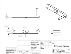 Image Added
| newwindow |
|---|
| Higher Resolution Image |
|---|
| Higher Resolution Image |
|---|
|
https://confluence.cornell.edu/download/attachments/82384572/crankDiagram.jpg?version=1 |
Using ANSYS, determine the mechanical response due to a load of 100 lbf applied vertically downward at the end of the pedal shaft as shown in the figure below. Assume that the crank is attached rigidly to a fixed shaft fitted into the hole near the left end of the crank. This means you can constrain the surface of the left hole in X, Y and Z directions as indicated below.
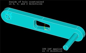 Image Added
Calculate the deflection, strain and stress distributions in the crank/pedal shaft combination for this loading condition. Use the ANSYS results to evaluate the degree of stress concentration in the vicinity of the cut-out in the crank geometry.
Go to Step 1: Start-up and preliminary set-up
See and rate the complete Learning Module
Go to all ANSYS Learning Modules
 Sign-up for free online course on ANSYS simulations!