 Sign-up for free online course on ANSYS simulations!
| HTML |
|---|
<div style="background-color: yellow; border: 2px solid red; margin: 4px; padding: 2px; font-weight: bold; text-align: center;">
This page has been moved to <a href="https://courses.ansys.com/index.php/courses/turbulent-forced-convection/">https://courses.ansys.com/index.php/courses/turbulent-forced-convection/</a>
<br>
Click in the link above if you are not automatically redirected in 10 seconds.
</div>
<meta http-equiv="refresh" content="10; URL='https://courses.ansys.com/index.php/courses/turbulent-forced-convection/'" /> |
| Include Page | ||
|---|---|---|
|
...
|
| Include Page | ||
|---|---|---|
|
...
|
Turbulent Forced Convection
Created using ANSYS 14.0
| Note |
|---|
This tutorial has videos. If you are in a computer lab, make sure to have head phones. |
Problem Specification

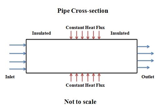
This tutorial will shows you how to model a simulate forced convection in a pipe using ANSYS FLUENT. The simulation corresponds to the forced convection experiment in MAE 4272 at Cornell University. The diagram shows a pipe where with a heated section in the middle , there is a heated sectionwhere constant heat flux is added at the wall. The ambient air is flowing into the pipe from the left with a uniform velocity. What will be the steady state temperature at the outlet of the pipe? How will the temperature change along the pipe? We will tackle all these questions in our simulation.
Available Information
We'll use FLUENT to solve the relevant boundary-value problem and obtain the velocity, temperature, pressure and density distribution in the pipe. Inputs necessary for the simulation, such as the velocity at the pipe inlet and heat flux added at the wall, are obtained from one particular experimental run. Results from the simulation will be compared with corresponding experimental values.
Handout: Powerpoint slides used in the videos
Simulation Inputs Obtained from Experiment
The following inputs are necessary to specify the domain, boundary conditions and material properties for the Boundary Value Problem (BVP) that we'll solve using FLUENT.
Pipe Geometry:
Circular cross-sectionPipe Geometry:
Pipe radius = 2.94e-2 m
Pipe length = 6.096 045 m
Air Material Properties:
Ambient pressure = 98338.2 Pa (Use as reference pressure)
Coeff. of viscosity = 1.787e-5 kg/(m s)
Cp = 1005 J/(kg K)
Thermal conductivity = 0.0266 W/(m K)
Molecular weight = 28.97 g/mole
Inlet:
• u = 2530.05 06 m/s
• v = 0 m/s
• T = 298.15 K
• k = 0.09 m2/s2; epsilon = 16 m2/s3 (These are not measured and are rough guess values)
Outlet:
• Pressure = 97225.9 Pa
Wall:
• Heating between x = 1.83 m and x = 4.27 m
• Wall heat flux = 34735210.9 85 W/m2
• Wall roughness: 0 (assume smooth)
• Wall thickness: 0 (assume negligible)
Ambient conditions:
• Ambient pressure = 98338.2 Pa
Go to Step 1: Pre-Analysis & Start-UpSee and rate the complete Learning Module