 Sign-up for free online course on ANSYS simulations!
Author: Rajesh Bhaskaran & Yong Sheng Khoo, Cornell University
Problem Specification
1. Pre-Analysis & Start-Up
2. Geometry
3. Mesh
4. Physics Setup
5. Numerical Solution
6. Numerical Results
7. Verification & Validation
Exercises
Comments
Geometry
Note to Cornell students enrolled in MAE 4272: You can skip the geometry and mesh steps. Download the mesh here. Unzip the downloaded file. After unzipping, you should see a file called pipe_flow.wbpj and a folder called pipe_flow_files. Double click on pipe_flow.wbpj and then skip to Step 4: Setup (Physics).
Since our problem involves fluid flow, we will select the FLUENT component on the left panel.
Left click (and hold) on Fluid Flow (FLUENT), and drag the icon to the empty space in the Project Schematic . Here's what you get:

Since we selected Fluid Flow (FLUENT), each cell of the system corresponds to a step in the process of performing CFD analysis using FLUENT. Rename the project to Forced Convection.
We will work through each step from top down to obtain the solution to our problem.
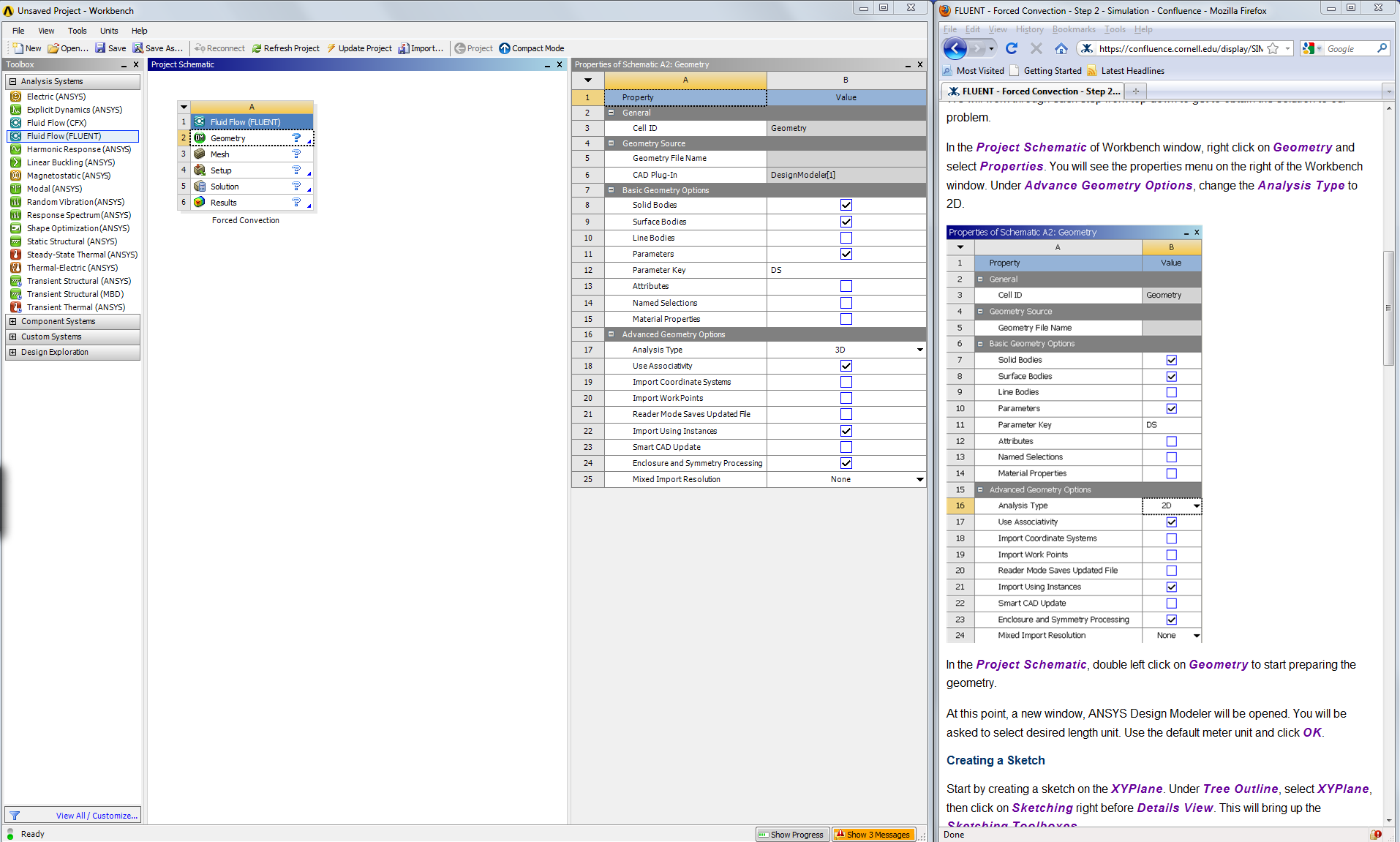
In the Project Schematic of the Workbench window, right click on Geometry and select Properties . You will see the properties menu on the right of the Workbench window. Under Advanced Geometry Options , change the Analysis Type to 2D.

In the Project Schematic , right click on Geometry and select Create New DesignModeler Geometry to start preparing the geometry. To make best use of screen real estate, move the windows around and resize them so that you approximate
At this point, ANSYS DesignModeler will open in a new window. You will be asked to select the desired length unit. Use the default meter unit and click OK .
The geometry is a rectangle of length L = 6.045m and height R = 2.94 x 10^-2 m .
Creating a Sketch
For users of ANSYS 15.0, please check this link for procedures for turning on the Auto Constraint feature before creating sketches in DesignModeler.
Start by creating a sketch on the XYPlane . Under Tree Outline , select XYPlane , then click on Sketching right before Details View . This will bring up the Sketching Toolboxes .

Click on the +Z axis on the bottom right corner of the Graphics window to have a normal look of the XY Plane.
In the Sketching toolboxes, select Rectangle . Hover the cursor near the origin until you see a letter P. This means the cursor is coincident with a point, in this case the origin . Then drag the cursor to draw a rectangle.

Note: You do not have to worry about dimensions for now, we will specify them properly in the later step.
Modify the Sketch
Since we have a heated section in the middle of the pipe, we need to split the geometry appropriately. Click Modify tab and select Split . Select two points at the top of the rectangle, where there will be a heated section. Then select two points at the bottom of the rectangle.
Now we can constraint the lower rectangle with the top of the rectangle. Click Constraints tab, select Equal Length . Click the appropriate top and bottom edge and set them to be of equal length. This is shown below:


Dimensions
Under Sketching Toolboxes , select Dimensions tab, use the default dimensioning tools. Then click on the lines and drag upwards or sideways as the case may be to place the dimensions (V1, H2, H3, H4). Note: For horizontal dimensioning (shown in H2, H3 and H4), click first on the horizontal dimension tab under the dimensions tab and then click (turns yellow) on the end points of the split section lines (H2, H3 and H4). Then click on any point on the y-axis and drag up. For the vertical dimensioning (V1), click on the vertical dimension tab under the dimensions tab. Then click on the any point on the x-axis then click on V1 (turns yellow). Then drag V1 to the left side.
Dimensioning of the geometry is shown below:

Under Details View in the lower left corner, input the values for the appropriate dimensions. Then hit enter each time each dimension is entered.
V1: 0.0294 m
H2: 1.83 m
H3: 4.27 m
H4: 6.045 m
At this point, you should see something like this for your sketch:

Now that we have the sketch done, we can create a surface for this sketch.
Then click on the Concept tab in the DesignModeler window, then click on Surface from sketches .
This will create a new surface SurfaceSK1 . Under the Tree Outline , click on the X-Y Plane and select Sketch1 as Base Objects and under Details View , click A pply . Finally click Generate to generate the surface.
Remember to save the project: File > Save Project
You can close the Design Modeler and go back to Workbench .
Go to Step 3: Mesh
Go to all FLUENT Learning Modules