 Sign-up for free online course on ANSYS simulations!
...
Only the area corresponding to this face is selected currently. Verify this by clicking Replot in the Select Entities menu (this replots areas).
One key think thing to remember about ANSYS' "select logic" is that the various entity types (areas, volumes, nodes, elements, etc) are selected independently. So all nodes are still "selected", not just the ones that are located on the front face of the crank. Verify this: Utility Menu > Plot > Nodes.
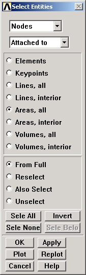
So we now need to We next select the nodes attached to the previously selected area. In the Select Entities menu, select Nodes from the pull-down menu at the top and Attached to below that. Select Areas, All below that. Click Apply.
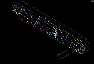
Check that only nodes attached to the front face are currently selected by clicking Replot in the Select Entities menu (this replots areasnodes).
We can get a better idea of where these nodes are located by plotting nodes as well as lines.
Utility Menu > PlotCtrls > Multi-Plot Controls ... > OK
Select Lines and Nodes and click OK.
Utility Menu > Plot > Multi-Plots
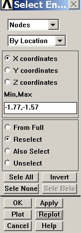
From these currently selected nodes, we next select nodes that satisfy the following criterion: -1.77"≤ x≤ -1.57". In the Select Entities menu, retain Nodes at the top. Select By Location and X coordinates below that. Enter Min,Max values as per below. Since we want the nodes to be selected from the current set rather than the full set, choose the Reselect radio button. Click Apply and then Replot.
Go to Step 9: Validate the results
See and rate the complete Learning Module
...