 Sign-up for free online course on ANSYS simulations!
| Include Page | ||||
|---|---|---|---|---|
|
Step 6: Results
...
Let first look at Total Deformation. Under Solution (A6), click on Total Deformation. The Total Deformation plot is then shown in the Graphics window.
...
You can also animate the deformation by clicking play button right under Graphics window.
Bending Stress
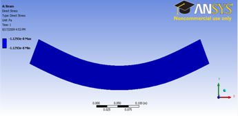
Now let's look at the stress on the beam. Let's expand Beam Tools and click on Direct Stress.
| newwindow | ||||
|---|---|---|---|---|
| ||||
https://confluence.cornell.edu/download/attachments/112041751/Direct%20Stress.png |
The direct stress is the stress component due to axial load encountered by the beam element. Since there is not axial load, we expect a direct stress of zero value throughout the beam.
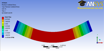
Next let's look at the Maximum Bending Stress of the beam. Click on Maximum Combined Stress.
| newwindow | ||||
|---|---|---|---|---|
| ||||
https://confluence.cornell.edu/download/attachments/112041761/Maximum%20Bending%20Stress.png |
Maximum Combined Stress is combination of direct stress and maximum bending stress. Since we have pure bending problem, the maximum combined stress will be the maximum bending stress.
We expect a pure bending stress in the central region between the two applied forces. The stress is tensile on the bottom surface and compressive on the top surface as expected. Elementary beam theory predicts the bending stress as σxx =My/I. Here
...
Force Reaction, Moment Reaction
If we click on the Force Reaction, we see that the force reaction at point A and B is 4000, which is what we are expecting. The moment reaction at A and B is also zero, as expected.
...