 Sign-up for free online course on ANSYS simulations!
...
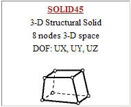
We next select the appropriate element type(s) for our problem from a large list of about 200 candidates. Consider this as equivalent to rifling through a sizable toolchest, picking out one or more tools and placing them on a table for later use (in step 5, in our case). To see which element types are appropriate for this problem, bring up the pictorial summary of element types: Utility menu > Help > Help Topics. Search for "pictorial summary" and double-click on the search result titled 3.2 Pictorial Summary. Click on the link to SOLID Elements. These are the element types you can use to mesh a solid volume. Check out the Solid45 element type. It is a brick-shaped element of the type referred to as "hexahedral" or "hex". It has a node at each corner and each node has three degrees of freedom: displacement in the x, y and z directions.
Click on the SOLID45 link in the pictorial summary. This takes you to the help page for this element. Read through the juicy information at the beginning of this help page. Note that there are no real constants to be defined in our case. Click on SOLID45 in the statement "See SOLID45 in the Theory Reference for ANSYS and ANSYS Workbench for more details about this element" which appears near the top of the help page. Click on Equation 12-188. This shows you the shape function for the element i.e. the equation used to determine the displacement at a general point within the element from the displacement values at the 8 nodes.
...
This is analogous to creating a sketch and then extruding while making a solid in a CAD package. Since we cannot mesh surfaces with SOLID45, we need an additional element type called MESH200. Go back to the pictorial summary of element types. Scroll to the top of the page and click on the link to MESH Elements. This takes you to the MESH200 element type.
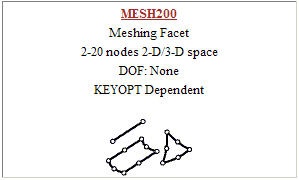
Click on the MESH200 link in the pictorial summary to see the help page for this element. You see the following information:
...
Referring to Figure 200.1 in the MESH200 help page, we see that this element type comes in 12 different flavors. For our purposes, we will be using the 3-D quadrilateral with 4 nodes option since this corresponds to an element face of SOLID45. The help page indicates that this option is selected by setting KEYOPT(1) = 6. Note that there are no real constants to be defined for MESH200.
...
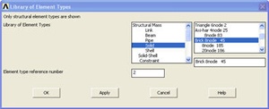
Main Menu > Preprocessor> Element Type > Add/Edit/Delete > Add...
Pick Structural Mass Solid in the left field and Brick 8node 45 in the right field. Click Apply to select this element.
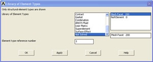
Scroll down the left field, pick Not Solved in this field and then Mesh Facet 200 in the right field. Click OK to select this element.
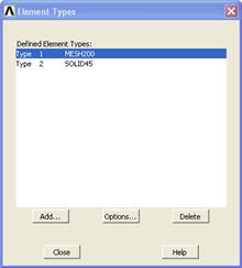
The Element Types window should list two types of elements: MESH200 and SOLID45.
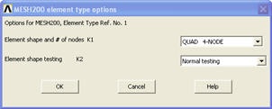
In order to set the 3-D quadrilateral with 4 nodes option for MESH200, click on MESH200 and then Options ... in the above menu. Then, select QUAD 4-NODE next to Element shape and # of nodes K1. Click OK.
Close the Element Types menu.
...