 Sign-up for free online course on ANSYS simulations!
Step 2: Mesh Geometry in GAMBIT
Mesh Faces
We will mesh each of the 2 faces separately to get our final mesh. Before we mesh a face, we need to define the point of distribution for each of the edges that form the face.
We will use the default setting for meshing of the edge.
Operation Toolpad > Mesh Command Button ![]() > Edge Command Button **
> Edge Command Button **  *> Mesh Edges*
 ![]()
Select the edge AB. The edge will change color and an arrow will appear on the edge. This indicates that you are ready to mesh this edge. Select interval size under Spacing. Enter 0.04 for interval size.
Next we will mesh the edge BC. Select the edge BC and enter 0.04 for interval size.
Do the same for edge CD and CF.
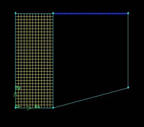
Now that the appropriate edge meshes have been specified, mesh the face face1:
Operation Toolpad > Mesh Command Button ![]() > Face Command Button
> Face Command Button ![]() > Mesh Faces
> Mesh Faces ![]()
Select the face1. The face will change color. You can use the defaults of Quad (i.e. quadrilaterals) and Map. Click Apply.
The meshed face should look as follows:

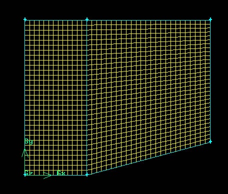
Next mesh face face2 in a similar fashion.
The resultant mesh should look as follows:

Note that for each mesh face, we only define 2 mesh edges. Gambit will automatically define the other two mesh edge for face mesh creation. Manual mesh of all edges can be done if more control of the mesh is required. Please refer to the index of the GAMBIT User Guide and look under Edge>Meshing for explanation on other type of meshing parameters.
Go to Step 3: Mesh