 Sign-up for free online course on ANSYS simulations!
Problem Specification
1. Create Geometry in GAMBIT
2. Mesh Geometry in GAMBIT
3. Specify Boundary Types in GAMBIT
4. Set Up Problem in FLUENT
5. Solve!
6. Analyze Results
7. Refine Mesh
Problem 1
Problem 2
Step 3: Specify Boundaries in GAMBIT
Label the boundaries according to the figure shown below.

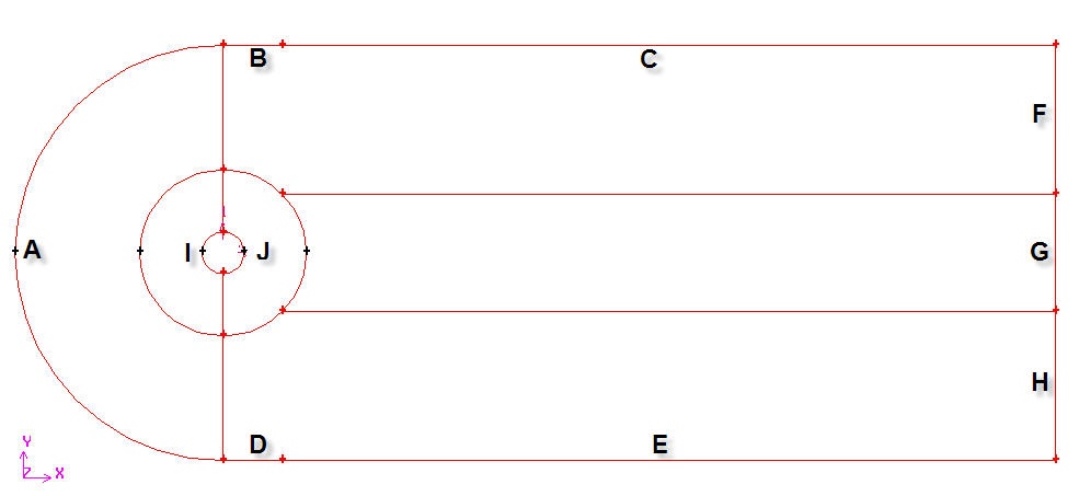
We will label edge A as farfield1, edges B and C as farfield2, edges D and E as farfield3, edges E,G and H as farfield4 and the edges I and J as cylinder.
Edges |
Name |
A |
farfield 1 |
B,C |
farfield 2 |
D,E |
farfield 3 |
F,G,H |
farfield 4 |
I,J |
cylinder |
Operation Toolpad > Zones Command Button ![]() > Specify Boundary Types
> Specify Boundary Types ![]()
Specify boundary according to the table above. Next to Name, enter the name accordingly. Leave the Type as WALL. We will specify boundary type using FLUENT.
Save Your Work
Main Menu > File > Save
Export Mesh
Main Menu > File > Export > Mesh...
Save the file as cylinder.msh.
Make sure that the Export 2d Mesh option is selected.
Check to make sure that the file is created.
Go to Step 4: Set Up Problem in FLUENT