Unknown macro: {composition-setup}
cloak.toggle.exclusive=false
Theory, Design, and Application of Gravity Powered Flow Controller
Authors: Monroe Weber-Shirk mw24@cornell.edu and Nicole Ceci
Unknown macro: {toggle-cloak}
Table of Contents
Unknown macro: {cloak}
Unknown macro: {cloak}
Abstract
Development of robust sustainable drinking water treatment technologies requires improved methods of metering aqueous chemical solutions. Existing technologies either required contact with the chemical solution when adjusting the flow rate or they didn't provide a calibrated method for setting the flow to the target value. The AguaClara team at Cornell University developed a low cost flow control module based on laminar pipe flow. The flow control module features a variable calibrated flow. The range of design flow rates is a function of the viscosity of the solution. For dilute solutions with viscosities similar to pure water the flow control modules can be designed in the range of 10 to 500 mL/min. The flow control module has been field tested for metering chlorine and aluminum sulfate for AguaClara water treatment plants in Honduras.
Keywords: Flow Controller, Laminar, Variable, Calibrated, AguaClara
Introduction
The lack of robust and sustainable technologies for chemical dosing and flow control that don't require electrical power continues to adversely affect the ability to reliably provide safe drinking water. Conventional municipal water treatment plants often use variable speed peristaltic pumps or other positive displacement pumps to meter coagulant solutions and chlorine. Many potential water treatment plant sites in the Global South don't have ready access to electricity and frequently the electrical grid is unreliable. The AguaClara team at Cornell University recognized the need for an improved gravity powered flow control device and began evaluating the available technologies and ultimately developed and tested an improved flow control module.
Unknown macro: {float}
[!flow controller theory^Hypochlorinator.jpg!]
Hypochlorinator design as implemented in hundreds of communities in Honduras. Frequently the float components are not included.
The AguaClara team first recognized the need for an improved flow control module during site visits of community water supply systems in Honduras in 2004. The standard Honduran design for community water supply systems consists of a surface water source that is piped to a distribution tank and then distributed via a pipe network to homes. The only water treatment is the addition of hypochlorite. Most communities use granular calcium hypochlorite to prepare a concentrated chlorine solution in a small tank that is located on top of the distribution tank. The original design of the hypochlorinators called for a floating frame that held a flexible tube with a submerged orifice. This system theoretically provided a constant flow through the submerged orifice. The orifice flow is set by the size of the orifice and the distance between the water (or chlorine) surface and the center of the orifice.
Unable to find DVI conversion log file. Orifice flowrate
where the orifice coefficient, K orifice has a value of approximately 0.6. In practice the orifices clog quickly due to the precipitation of calcium carbonate, the flow rate adjustment is by trial and error, and maintenance and operation requires contact with the concentrated chlorine solution. Perhaps due to these difficulties the design evolved and a 1/2" PVC valve was installed on the exit pipe at the bottom of the chlorine tank, the floating orifice was removed, and the flow is now adjusted by a trial and error setting of the valve position. This modification created a system that was easier to maintain, but the valve was still subject to frequent clogging and the hydraulic design no longer provided a constant flow. The flow decreases as the reservoir drains. The decrease in flow rate over time can be obtained by combining mass conservation and the orifice equation and integrating to find the reservoir depth as a function of time. If the operator sets the valve to deliver a flow rate such that the reservoir would drain in t design if the flow remained constant, then the flow rate will decrease significantly over the t design and by the end of the design period the theoretical flow is given by
Unable to find DVI conversion log file. Hypochlorinator Q vs t
where h res is the initial depth of chemical solution in the reservoir, h 0 is the vertical distance between the initial free surface and the orifice (the valve), t design is the duration that the chemical supply was supposed to last, and Q 0 is the initial flow rate from the valve. Thus if the valve is located at almost the same elevation as the bottom of the reservoir, then when t = t design the flow will be approximately one half of the design flow. If the operator allows the entire tank to drain without adjusting the flow rate there will be an even larger flow variation. The large fluctuation in chlorine flow rate increases the difficulty of maintaining an appropriate chlorine residual.

Another design for a constant flow device is called a floating bowl #Brikké and Bredero, 2003. It is conceptually similar to the hypochlorinators used in Honduras, but the flow is adjusted by varying the submergence of the bowl instead of by sliding the tube with the orifice relative to the floating frame. The submergence is varied by adding or removing pebbles from the bowl. The floating bowl also requires reaching into the chemical solution to adjust the pebbles. Adjustments to the flow rate can be calibrated to eliminate the need for trial and error. Both the floating bowl and the floating frame have to be installed inside each chemical tank that is used for chemical dosing.
The difficulties of using the current flow control devices prompted us to develop a list of characteristics required for the next generation of gravity powered flow control devices. An ideal flow control device would have the following characteristics:
- calibrated to easily vary the flow rate
- maintain a constant flow rate independent of the chemical level in the stock tank
- handle corrosive chemicals
- incorporate a linear scale to facilitate setting the flow without need to use trial and error
- be resistant to clogging
- be easy to maintain and operate
- be economical, small, and easily used to replace existing flow control devices
- be easily adapted for a range of flow rates
Theory
Maintaining a constant flow of chemical is difficult because of the fluctuations in the level of the chemical in the stock tank. The variable head means that any restrictions used to regulate the flow will cause a decreasing flow rate as the tank empties. One simple solution to this problem would be to use an elevated tank with a large head driving the fluid through the flow restriction. Then the small variation in the driving head as the tank emptied would not be as significant. The disadvantages of this approach are the construction and operation difficulties of the elevated tank and the clogging of the flow restriction. Thus we need a solution that isolates the flow restriction from the variable head of the stock tank and we need a flow restriction that is as large as possible to minimize clogging.
Creation of a constant flow requires a constant driving force coupled with a constant pressure coefficient or loss coefficient. Recent advances in small low cost chemical resistant float valves have made it possible to use float valves even with corrosive chlorine solutions. The float valve can be used to maintain a constant liquid level in a small tank. The constant liquid level can then be used to develop a constant flow when coupled with a constant pressure or loss coefficient. Many float valves are designed to cycle between full on and full off to minimize wear on the valve mechanism. These float valves wait for the water level to drop a significant amount (often more than 1 cm) before cycling on again. Thus these more sophisticated float valves would be a poor choice for a constant head tank. The ideal constant head tank float valve consists of a float on a lever that pushes a soft surface against an opening to close the opening.
There are many methods of creating a constant loss coefficient including flow through a valve, porous media, a long tube, or an orifice. Selection of an appropriate mechanism for producing the loss coefficient can be based on the desired characteristics of the flow control device. We have tested the use of a sand column to provide a loss coefficient for flow regulation. The sand column has the advantage of being able to handle some particle accumulation with minimal affect on the loss coefficient. The disadvantages of the sand column are that it must filled using up flow to prevent air entrapment and the cost of the assembly.
Clogging due to precipitation of calcium carbonate in the case of hypochlorinators, insoluble contaminants of aluminum sulfate, and particulate matter that may be present in the water used to prepare the chemical stocks is a significant problem. In the case of hypochlorinators clogging is a common failure mode. To reduce the risk of clogging the flow passage diameter should be as large as possible. The loss coefficient for valves and orifices are both due to the expansion losses that occur downstream from the flow restriction and thus the flow area is similar for valves and orifices given the same loss coefficient. The relationship between the orifice diameter and flow rate is derived from energy conservation. This equation is valid for both turbulent and laminar flow if the orifice or valve discharges to the atmosphere.
Unable to find DVI conversion log file. D orifice
The laminar flow relationship between head loss due to shear on the pipe walls (h f), pipe length (L), pipe diameter (D), and kinematic viscosity (¿) is given by the Hagen-Poiseuille equation.
Unable to find DVI conversion log file. D Hagen-Poiseuille
The maximum flow that can be sent through a tube while maintaining laminar flow is based on eliminating diameter from the Hagen-Poiseuille equation by using the maximum laminar flow Reynolds number constraint of 2100.
Unable to find DVI conversion log file. Maximum laminar flow
Unknown macro: {float}

Tube vs orifice diameter given a head loss of 20 cm and tube length of 1 m (need to confirm the flow conditions)
Plots of the orifice and pipe diameters as a function of flow rate reveal that the tube diameter is approximately 1 mm larger than the orifice or valve opening for the entire range of laminar flow. Although a 1 mm increase in diameter may not appear significant, the risk of clogging is substantially reduced because the sedimentation velocity for small particles is proportional to their projected area. The larger particles required to clog the tube are more easily removed by sedimentation in the stock tank or in the constant head tank.
A flexible tube can be used to regulate the flow from a constant head tank by simply raising or lowering the end of the tube that discharges to the atmosphere. Under conditions of laminar flow and neglecting entrance and exit losses, the flow rate is directly proportional to the difference in elevation between the liquid level in the constant head tank and the discharge end of the tube. The flow rate can be easily calibrated so that a particular flow can be reliably obtained by setting the elevation difference. The simple laminar flow tube is a significant improvement over a valve because the valve setting can not be easily replicated unless it has a dial indicating the valve position. The high cost of valves with position indicators in comparison with the cost of a short length of flexible tubing gives a strong advantage to the laminar flow tube.
It is likely possible to design a flow control module using turbulent pipe flow. However, we anticipate unfavorable flow fluctuations in the transition region between laminar and fully turbulent flow. A turbulent flow design would not have a linear response, but it could still be calibrated. We have not yet explored the use of turbulent flow designs because the flow rates that we have needed for the AguaClara can be accommodated using laminar flow.
Design of a flow control module initially appears difficult because of the flexibility to choose tube length, tube diameter, and head loss. Appropriate selection of the parameters to obtain a practical design is subject to a series of constraints. A clear physical constraint is set by the goal of maintaining laminar flow in the tube. The continuity equation (Q = VA) and the equation for the area of a circle can be substituted into the Reynolds number definition to obtain the minimum diameter required to obtain laminar flow for a given maximum design flow rate.
Unable to find DVI conversion log file. Minimum Diameter for Laminar Flow
The laminar flow constraint dictates that the tube diameter must increase as the maximum design flow increases. A second constraint on the tube diameter can be obtained based on the requirement that the tube must be long enough so that the end of the tube can reach the various elevations required to set the desired head loss. In subsequent analysis we assume that the end of the tube can reach high enough so that the flow can be set to zero and that it can reach low enough to obtain the maximum design flow. At absolute minimum the tube length would have to be longer than 1/2 the maximum head loss and given the need to have gentle curves in the tube a more reasonable constraint might be 1.5 times the maximum head loss. A desired relationship between head loss and tube length can be substituted into the Hagen-Poiseuille equation to give a second constraint on the tube diameter.
Unable to find DVI conversion log file. D Hagen-Poiseuille
Unknown macro: {float}

Minimum tube diameter given the three constraints of laminar flow, tube length sufficient to accommodate the head loss range, and a series of available tubing diameters. The constraints used were a maximum head loss of 20 cm, a minimum tube length of 30 cm, available tubing sizes in increments of 1 mm, and solution viscosity of pure water. The blue dot represents a design solution for a 200 mL/min flow rate.
The minimum diameter that can be used is the maximum diameter obtained from the previous two equations.
The design diameter of the tubing is obtained by selecting the smallest diameter tubing that is larger than the minimum diameter. The example design solution shows that the head loss constraint dominates for low flows and the laminar flow constraint dominates for higher flows. It is important to note that a single tube diameter can provide a wide range of maximum flow rates and that all designs have the capability of varying the flow from zero to the maximum design flow rate by simply raising the discharge end of the tube to the liquid level height in the constant head tank.
The next step in the design process is to determine the length of tubing. The tubing length is obtained by solving the Hagen-Poiseuille for tubing length given the design tube diameter, maximum design flow rate, and maximum design head loss. The maximum design head loss also is governed by several constraints.
The minimum value for the maximum head loss for a flow control device must be large enough so that it is easy for the operator to accurately adjust the tube position to set the flow rate. The accuracy of the flow rate is also affected by any fluctuations in the fluid level in the "constant" head tank. Although the fluid level is controlled by a float valve, the float valve does not completely isolate the constant head tank from variations in the level of the stock tank. The hydrostatic pressure exerted by the liquid in the stock tank must be resisted by the float valve and ultimately the force must be provided by the buoyancy of the float. Thus the extent of submergence of the float decreases as the stock tank empties and the liquid level in the constant head tank decreases slightly as well. We tested the attenuation ratio (the change in the constant head tank liquid level divided by the change in the stock tank level for the modified float valve that we use
The attenuation ratio can be obtained by a moment balance about the float valve hinge pin required to cause the valve to close.
Unable to find DVI conversion log file. flow controller moment balance
where Unable to find DVI conversion log file. is the change in depth of the liquid level in the constant head tank and Unable to find DVI conversion log file. is the cross sectional area of the cylindrical float. Thus Unable to find DVI conversion log file. is the submerged volume of the float that when multiplied by the density, Unable to find DVI conversion log file. and by acceleration due to gravity is equal to the total buoyant force acting on the float. The lever arm for the float has a length Unable to find DVI conversion log file.. The moment acting to open the valve is provided by the pressure of liquid from the stock tank, Unable to find DVI conversion log file., acting over the area of the valve opening Unable to find DVI conversion log file.. The lever arm for the opening moment is Unable to find DVI conversion log file..
The float valve attenuation can be obtained by rearranged the previous equation and solving for the ratio of the change in height of the stock tank divided by the change in height of the constant head tank.
Unable to find DVI conversion log file. Float valve attenuation
The theoretical attenuation factor for the miniature PVC adjustable float valve modified with a 5 cm diameter polypropylene float is approximately 2000. The attenuation factor was also measured. A peristaltic pump was connected to the inlet of the flow controller, along with a pressure sensor. The outlet tube of the flow controller was plugged. The peristaltic pump was then used to pump water into the flow controller. The pressure of the water in the inlet tube, or the pressure the float valve could resist, was then measured using process controller. The maximum inlet pressure was determined using three orientations, with the float straight down giving the lever arm a 90 degree angle, partially down for a 45 degree angle, and straight out at zero degrees. This was to determine which orientation provided the greatest resistance. The pressure was also measured as a function of the height of the water level inside the flow controller. The results indicate that the attenuation factor is similar for the different orientations of the float valve and thus we selected the orientation with float axis vertical to the water surface since that is the most compact orientation for installation inside a 1 liter bottle. The measured attenuation factor is approximately 900. Thus a change in liquid level of 1 m in the stock tank is expected to only produce a change of approximately 1 mm in the flow controller.
Unknown macro: {float}
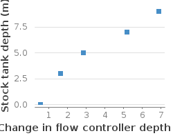
Attenuation factor for the float valve with the 5 cm diameter polypropylene float installed with its axis vertical.
In addition the desired increments in flow settings must be

Application
The AguaClara project team began using the
flow control module design webpage

Flow control modules will generate a linear response between head loss and chemical flow rate as long as expansion losses are small relative to shear losses and as long as the flow is laminar.
Design of the flow control module consists of choosing a maximum head loss corresponding to the maximum design flow rate, and then determining the diameter and length of the tubing.
Cost
parts list and cost
Conclusion
Acknowledgments
The development of the Flow Controller began as a class project in the course Sustainable Small Scale Water Supplies in the fall of 2004. The entire class contributed by testing various flow control ideas and the simple float valve and tube became the clear favorite for further investigation. The first field implementation of the flow controller was by Roslyn Odum in the Honduran community of La 34, the site of the first AguaClara water treatment plant. A number of AguaClara team members tested various float valve configurations before we discovered the manufactured PVC float valve that we now use. The manufactured PVC float valve was tested in the laboratory by Nicole Ceci, Cherish Scott, and ???. The 1 liter bottle version of the flow controller was first tested on aluminum sulfate and chlorine feed systems in the Honduran community of Ojojona, site of the second AguaClara water treatment plant. The Ojojona plant operators, ?? took the initiative to use the flow controller to upgrade an existing chlorine feed system and thus began the first replacement of the traditional hypochlorinators. The Sanjuan Fund generously supported the research and testing of the flow controller.
References
* François Brikké and Maarten Bredero © World Health Organization and IRC Water and Sanitation Centre, 2003 Linking technology choice with operation and maintenance in the context of community water supply and sanitation: A reference document for planners and project staff Chapter 6 Water Treatment.