| Name | Size | Creator | Creation Date | Labels | Comment | ||
|---|---|---|---|---|---|---|---|
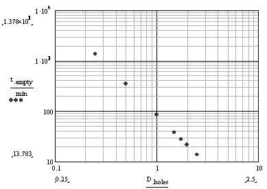
| JPEG File draining time vs diameter.JPG | 20 kB | user-67307 | May 14, 2008 20:34 |
|
function describing tank draining time as a function of orifice diameter | ||
| Version 1 (current) | 20 kB | user-67307 | May 14, 2008 20:34 | function describing tank draining time as a function of orifice diameter | |||
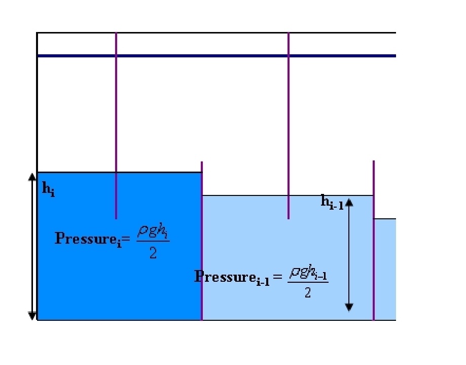
| JPEG File baffle force.JPG | 76 kB | user-67307 | May 14, 2008 20:33 |
|
picture explaining the force on a baffle during draining | ||
| Version 1 (current) | 76 kB | user-67307 | May 14, 2008 20:33 | picture explaining the force on a baffle during draining | |||
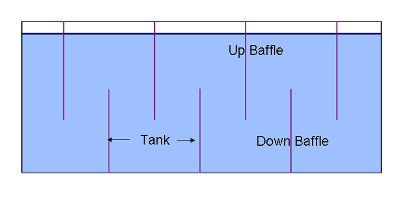
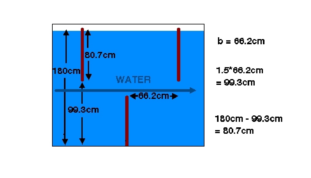
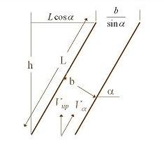
| JPEG File baffle layout.JPG | 84 kB | user-67307 | May 14, 2008 20:33 |
|
picture defining the terms "up baffle" and "down baffle" | ||
| Version 1 (current) | 84 kB | user-67307 | May 14, 2008 20:33 | picture defining the terms "up baffle" and "down baffle" | |||
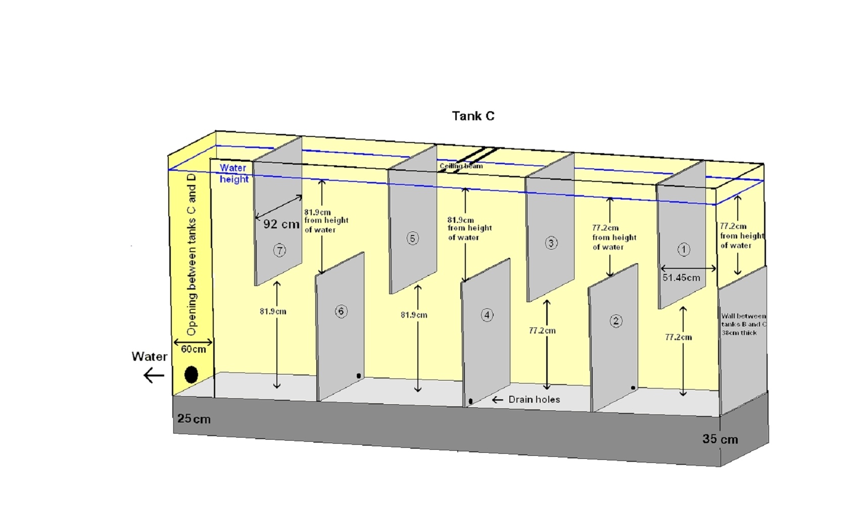
| JPEG File tank C baffles.jpg | 260 kB | user-67307 | May 14, 2008 20:32 |
|
picture showing baffle locations in tank C | ||
| Version 1 (current) | 260 kB | user-67307 | May 14, 2008 20:32 | picture showing baffle locations in tank C | |||
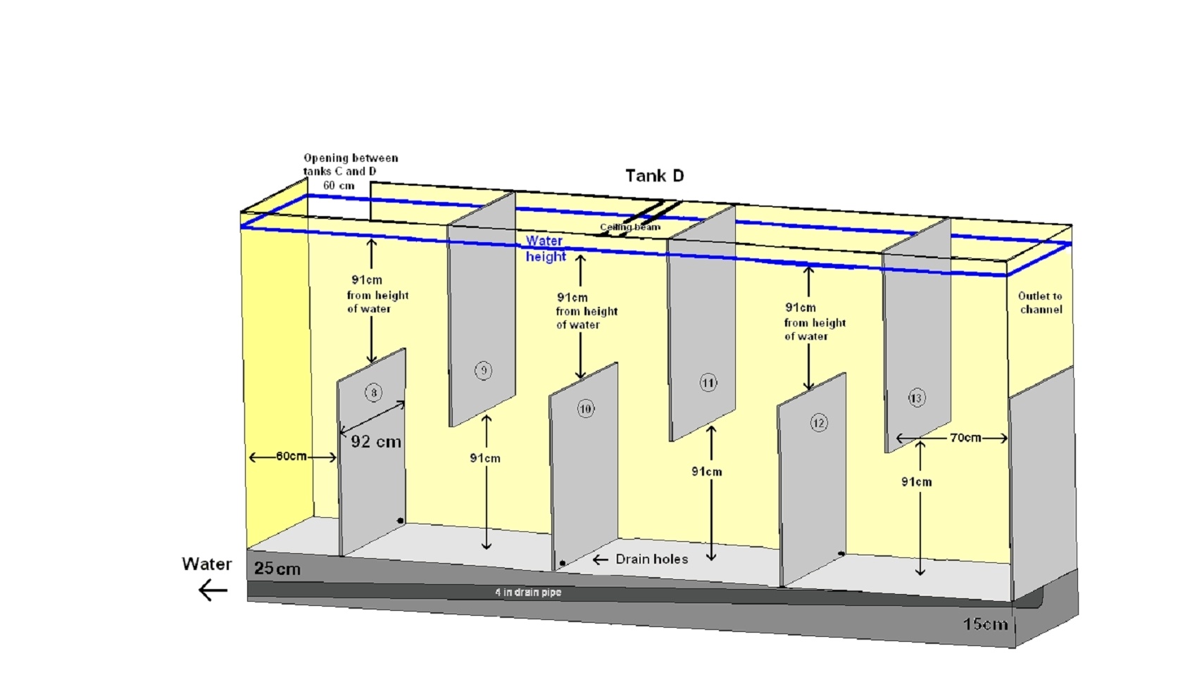
| JPEG File tank D baffles.jpg | 258 kB | user-67307 | May 14, 2008 20:32 |
|
picture showing baffle locations in tank D | ||
| Version 1 (current) | 258 kB | user-67307 | May 14, 2008 20:32 | picture showing baffle locations in tank D | |||
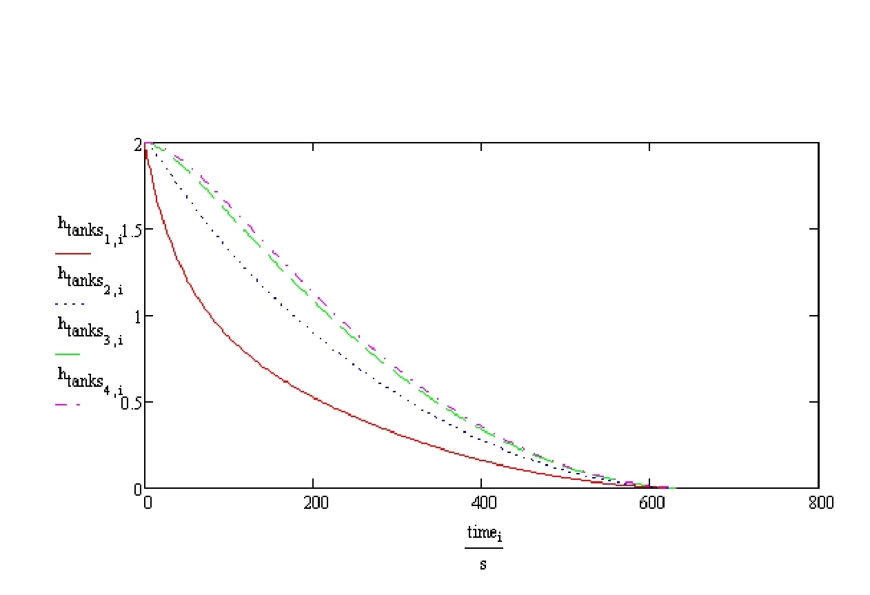
| JPEG File tank draining time.jpg | 110 kB | user-67307 | May 14, 2008 20:30 |
|
graph showing the difference in draining time for each tank in the flocculator | ||
| Version 1 (current) | 110 kB | user-67307 | May 14, 2008 20:30 | graph showing the difference in draining time for each tank in the flocculator | |||
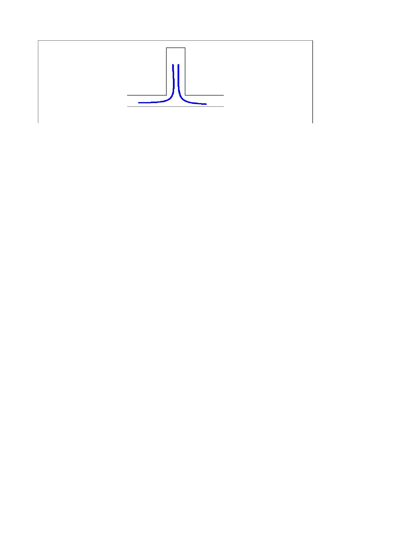
| JPEG File short circuit.jpg | 85 kB | user-67307 | May 14, 2008 20:29 |
|
diagram explaining occurence of short circuiting at the end of the tank | ||
| Version 1 (current) | 85 kB | user-67307 | May 14, 2008 20:29 | diagram explaining occurence of short circuiting at the end of the tank | |||
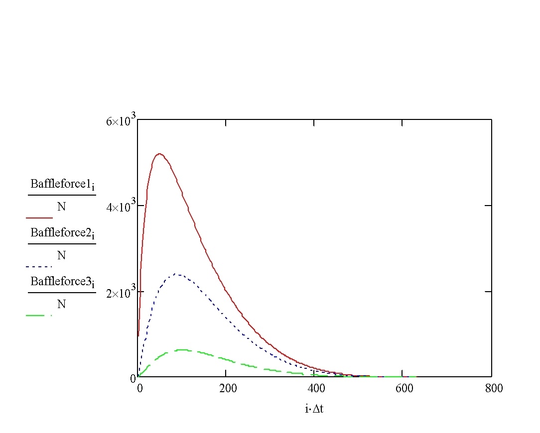
| JPEG File force on walls.jpg | 102 kB | user-67307 | May 14, 2008 20:29 |
|
graph of forces on the baffles during draining | ||
| Version 1 (current) | 102 kB | user-67307 | May 14, 2008 20:29 | graph of forces on the baffles during draining | |||
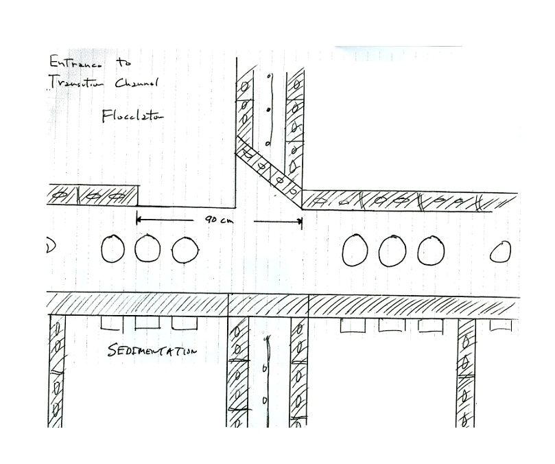
| JPEG File transition chamber_top view.jpg | 215 kB | user-67307 | May 13, 2008 01:55 |
|
top view of the channel between the floc and sed tanks | ||
| Version 1 (current) | 215 kB | user-67307 | May 13, 2008 01:55 | top view of the channel between the floc and sed tanks | |||
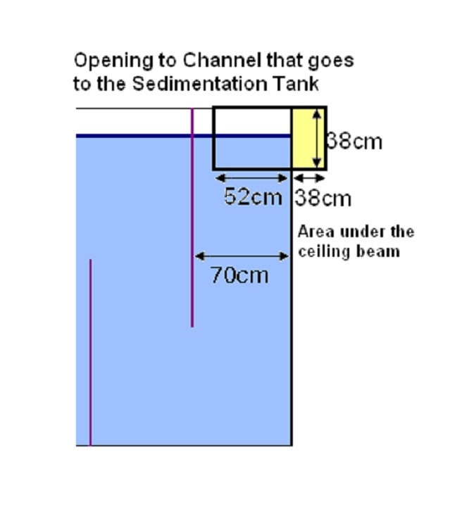
| JPEG File transition chamber_side view.jpg | 69 kB | user-67307 | May 13, 2008 01:54 |
|
side view of the channel between floc and sed tanks | ||
| Version 1 (current) | 69 kB | user-67307 | May 13, 2008 01:54 | side view of the channel between floc and sed tanks | |||
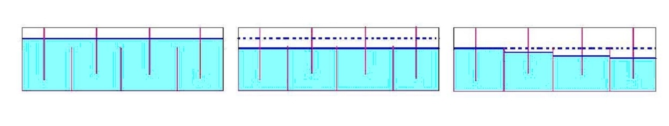
| JPEG File tanks draining.jpg | 102 kB | user-67307 | May 13, 2008 01:52 |
|
Sed tanks draining | ||
| Version 1 (current) | 102 kB | user-67307 | May 13, 2008 01:52 | Sed tanks draining | |||
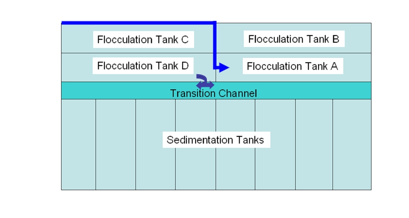
| JPEG File Microsoft Word - MARCALA 12 v4.jpg | 78 kB | user-67307 | Apr 30, 2008 18:40 |
|
PIcture of Transition Channel | ||
| Version 1 (current) | 78 kB | user-67307 | Apr 30, 2008 18:40 | PIcture of Transition Channel | |||
| Multimedia File Marcala Draining.avi | 728 kB | user-67307 | Mar 12, 2008 21:39 |
|
video of flocculators draining | ||
| Version 1 (current) | 728 kB | user-67307 | Mar 12, 2008 21:39 | video of flocculators draining | |||
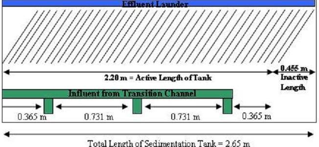
| JPEG File sedimenationtankparameters.JPG | 44 kB | user-9e1cf | Mar 03, 2008 12:10 |
|
Marcala Sedimentation Tank Parameters | ||
| Version 1 (current) | 44 kB | user-9e1cf | Mar 03, 2008 12:10 | Marcala Sedimentation Tank Parameters | |||
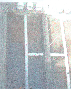
| JPEG File SludgeRemovalSystempic.jpg | 311 kB | user-9e1cf | Mar 03, 2008 12:10 |
|
Marcala Sludge Revoval System Picture | ||
| Version 1 (current) | 311 kB | user-9e1cf | Mar 03, 2008 12:10 | Marcala Sludge Revoval System Picture | |||
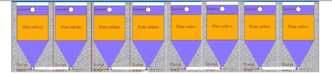
| JPEG File SludgeRemovalSystem.jpg | 173 kB | user-9e1cf | Mar 03, 2008 12:09 |
|
Marcala Sludge Removal System Diagram | ||
| Version 1 (current) | 173 kB | user-9e1cf | Mar 03, 2008 12:09 | Marcala Sludge Removal System Diagram | |||
| JPEG File Microsoft Word - MARCALA 12.jpg | 6 kB | user-9e1cf | Feb 29, 2008 15:52 |
|
Mathematical Parameters | ||
| Version 1 (current) | 6 kB | user-9e1cf | Feb 29, 2008 15:52 | Mathematical Parameters | |||
| File Flocculator Design Program.xmcd | 530 kB | user-67307 | Feb 28, 2008 19:43 |
|
Flocculator Design Program | ||
| Version 1 (current) | 530 kB | user-67307 | Feb 28, 2008 19:43 | Flocculator Design Program | |||
| File Floc Draining Time with Forces Calculated 3 - FINAL.xmcd | 344 kB | user-67307 | Feb 28, 2008 19:43 |
|
Flocculator Draining Time | ||
| Version 1 (current) | 344 kB | user-67307 | Feb 28, 2008 19:43 | Flocculator Draining Time | |||
| JPEG File Marcala Plant layout.jpg | 181 kB | user-67307 | Feb 28, 2008 19:43 |
|
marcala plant layout | ||
| Version 1 (current) | 181 kB | user-67307 | Feb 28, 2008 19:43 | marcala plant layout |
Attachments
Overview
Content Tools