| Name | Size | Creator | Creation Date | Labels | Comment | ||
|---|---|---|---|---|---|---|---|
| PDF File ACD F08 Dimensions Needed 11.30.08.pdf | 52 kB | user-dd1ec | Nov 30, 2008 14:05 |
|
Labeled AutoCAD drawing of Tamara Entrance tank showing dimensions still needed by ACD team 11.30.08 | ||
| Version 1 (current) | 52 kB | user-dd1ec | Nov 30, 2008 14:05 | Labeled AutoCAD drawing of Tamara Entrance tank showing dimensions still needed by ACD team 11.30.08 | |||
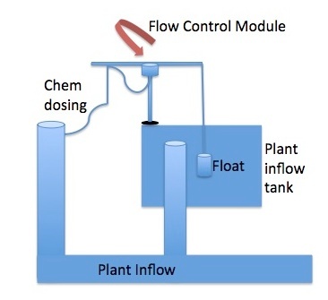
| JPEG File ACDF08 Labeled Context View.jpg | 25 kB | user-dd1ec | Nov 30, 2008 14:05 |
|
Side view labeled diagram of Fall08 Automated Chem Doser in contex of Tamara plant | ||
| Version 1 (current) | 25 kB | user-dd1ec | Nov 30, 2008 14:05 | Side view labeled diagram of Fall08 Automated Chem Doser in contex of Tamara plant | |||
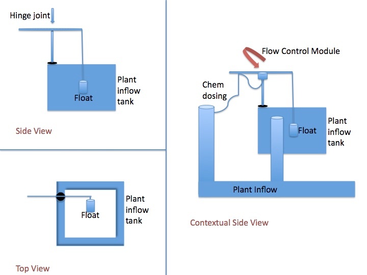
| JPEG File ACDF08 Labeled Sketch.jpg | 51 kB | user-dd1ec | Nov 30, 2008 14:05 |
|
Side view, top view, and contextual labeled diagrams of Fall08 Automated Chem Doser | ||
| Version 1 (current) | 51 kB | user-dd1ec | Nov 30, 2008 14:05 | Side view, top view, and contextual labeled diagrams of Fall08 Automated Chem Doser | |||
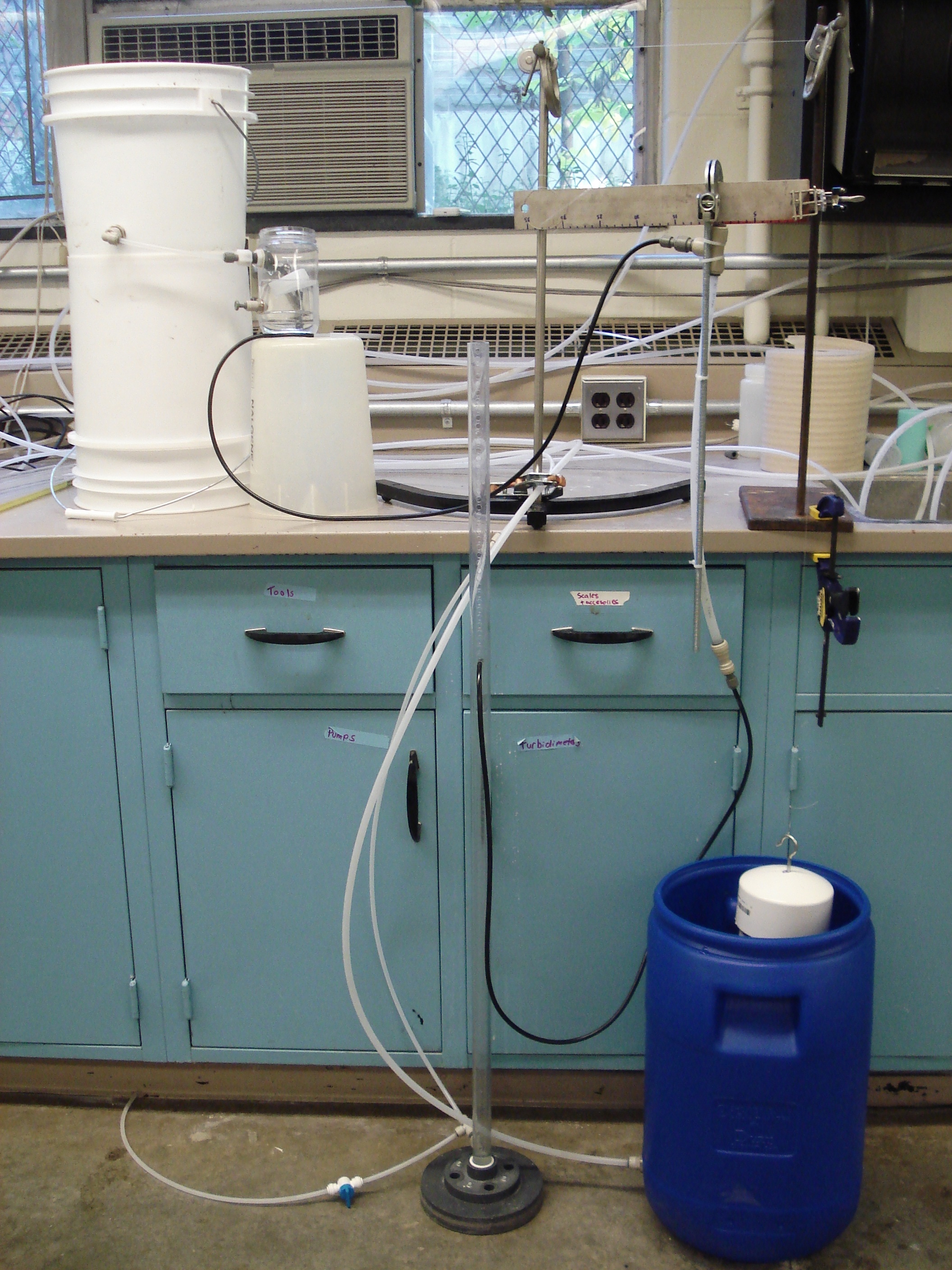
| File ACD set up.JPG | 3.35 MB | user-dd1ec | Oct 20, 2008 16:37 |
|
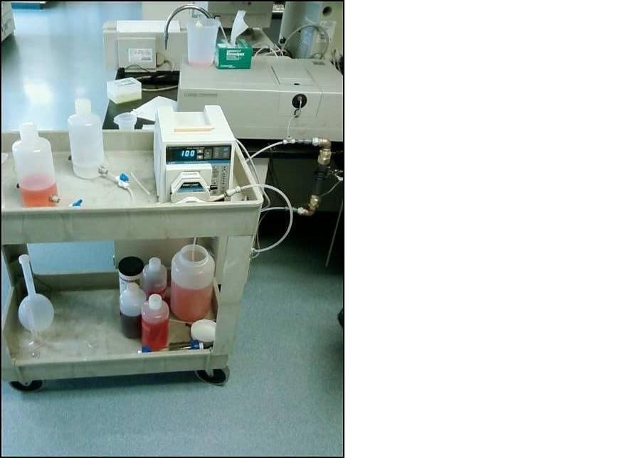
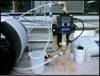
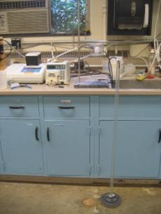
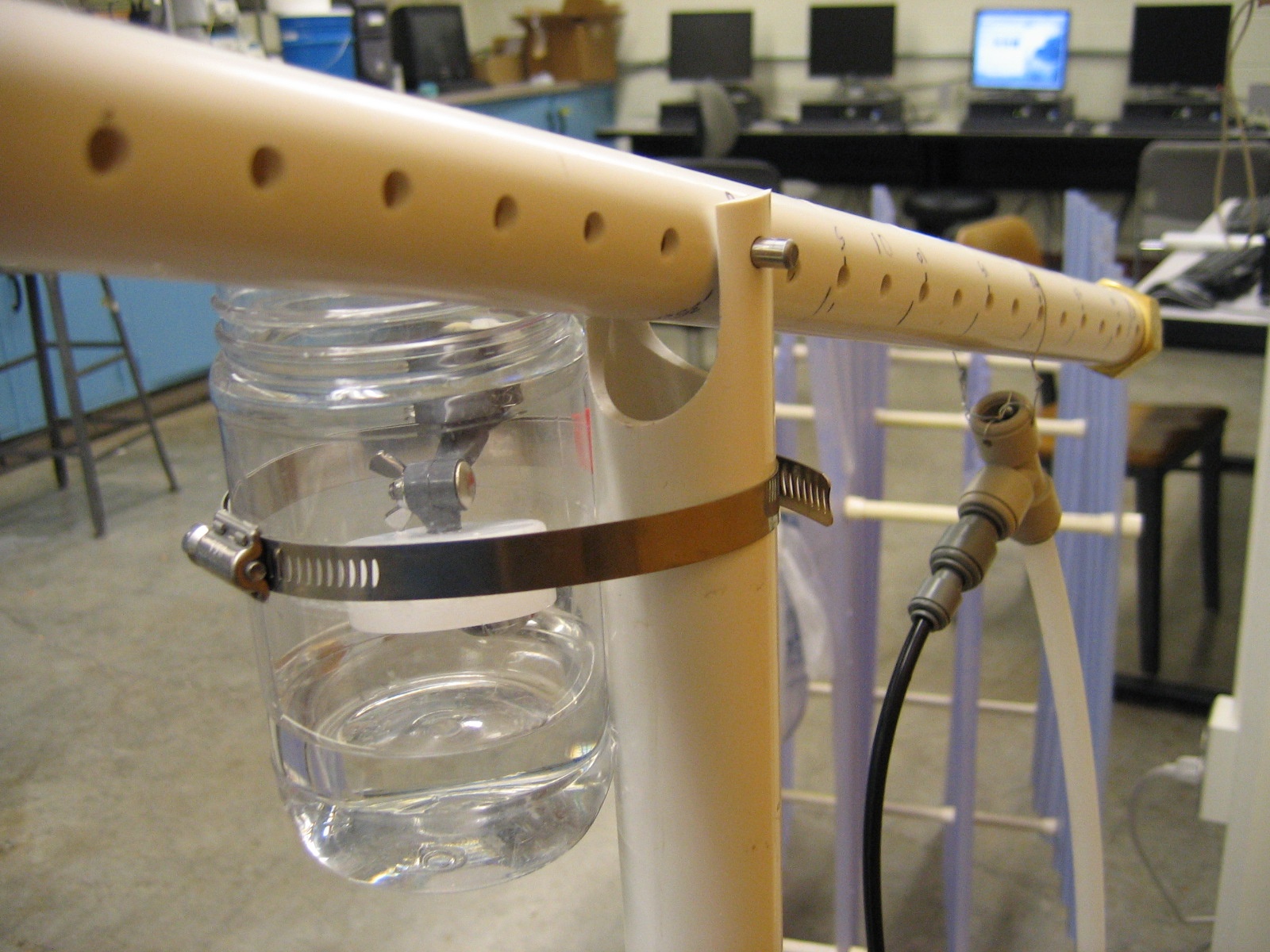
Automated chem doser experimental set-up from October 2008 (with disconnected FCM) | ||
| Version 1 (current) | 3.35 MB | user-dd1ec | Oct 20, 2008 16:37 | Automated chem doser experimental set-up from October 2008 (with disconnected FCM) | |||
| File ACD set up labeled.JPG | 627 kB | user-dd1ec | Oct 20, 2008 16:52 |
|
Labeled pic of automated chem doser experimental set-up from October 2008 (with disconnected FCM) | ||
| Version 1 (current) | 627 kB | user-dd1ec | Oct 20, 2008 16:52 | Labeled pic of automated chem doser experimental set-up from October 2008 (with disconnected FCM) | |||
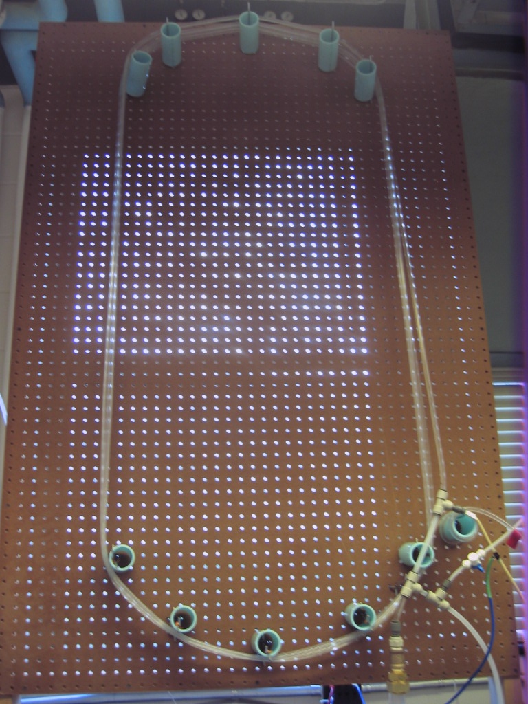
| File board.JPG | 284 kB | user-ec56f | Apr 18, 2008 16:48 |
|
Tube Floc - Just the Board Flocculator | ||
| Version 2 (current) | 284 kB | user-ec56f | Apr 18, 2008 16:48 | Tube Floc - Just the Board Flocculator | |||
| Version 1 | 284 kB | user-ec56f | Apr 18, 2008 16:46 | Tube Floc - Board Flocculator | |||
| File Board and ET.JPG | 229 kB | user-ec56f | Apr 18, 2008 16:48 |
|
Tube Floc - Board Flocculator and Effluent Turbidimeter | ||
| Version 1 (current) | 229 kB | user-ec56f | Apr 18, 2008 16:48 | Tube Floc - Board Flocculator and Effluent Turbidimeter | |||
| File board-top.JPG | 160 kB | user-ec56f | Apr 18, 2008 16:48 |
|
Tube Floc - Board Flocculator - top | ||
| Version 1 (current) | 160 kB | user-ec56f | Apr 18, 2008 16:48 | Tube Floc - Board Flocculator - top | |||
| JPEG File Dye Test setup.jpg | 45 kB | user-ec56f | Feb 14, 2008 12:22 |
|
Tube Floc - Dye Test Setup | ||
| Version 1 (current) | 45 kB | user-ec56f | Feb 14, 2008 12:22 | Tube Floc - Dye Test Setup | |||
| JPEG File Floc Setup.jpg | 186 kB | user-27d2e | Feb 05, 2008 13:51 |
|
Tube Floc- Lab setup | ||
| Version 1 (current) | 186 kB | user-27d2e | Feb 05, 2008 13:51 | Tube Floc- Lab setup | |||
| JPEG File FlowControlDrawing.jpg | 16 kB | user-dd1ec | Sep 04, 2008 21:11 |
|
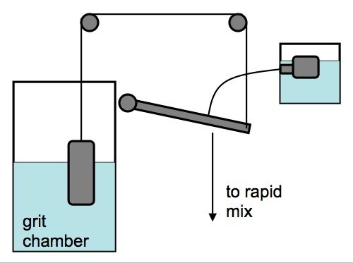
Drawing of proposed schematic for automatic flow and chemical dosing system | ||
| Version 1 (current) | 16 kB | user-dd1ec | Sep 04, 2008 21:11 | Drawing of proposed schematic for automatic flow and chemical dosing system | |||
| JPEG File Heat test setup.jpg | 19 kB | user-ec56f | Feb 14, 2008 12:19 |
|
Tube Floc - Heat Test setup | ||
| Version 1 (current) | 19 kB | user-ec56f | Feb 14, 2008 12:19 | Tube Floc - Heat Test setup | |||
| JPEG File image001.jpg | 5 kB | user-dd1ec | Feb 04, 2008 02:16 |
|
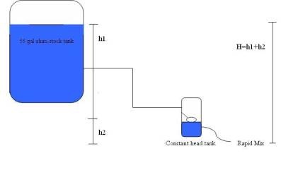
FCM- Overview of the alum dosing system where H equals the vertical distance between the alum level in the 55 gal stock tank and the effluent location, where alum enters the rapid mix. | ||
| Version 1 (current) | 5 kB | user-dd1ec | Feb 04, 2008 02:16 | FCM- Overview of the alum dosing system where H equals the vertical distance between the alum level in the 55 gal stock tank and the effluent location, where alum enters the rapid mix. | |||
| JPEG File image002.jpg | 6 kB | user-dd1ec | Feb 04, 2008 02:16 |
|
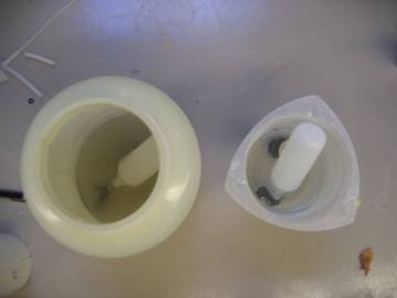
FCM- Top-down view of the float valves in chlorine (left) and alum solutions (right) for the corrosion testing (Fall 2007). | ||
| Version 1 (current) | 6 kB | user-dd1ec | Feb 04, 2008 02:16 | FCM- Top-down view of the float valves in chlorine (left) and alum solutions (right) for the corrosion testing (Fall 2007). | |||
| JPEG File image003.jpg | 10 kB | user-dd1ec | Feb 04, 2008 02:17 |
|
FCM- The column experimental set up for determining the relationship between flow rate and headloss (Fall 2007). | ||
| Version 1 (current) | 10 kB | user-dd1ec | Feb 04, 2008 02:17 | FCM- The column experimental set up for determining the relationship between flow rate and headloss (Fall 2007). | |||
| File IMG_7223.JPG | 602 kB | user-dd1ec | Dec 09, 2008 00:32 |
|
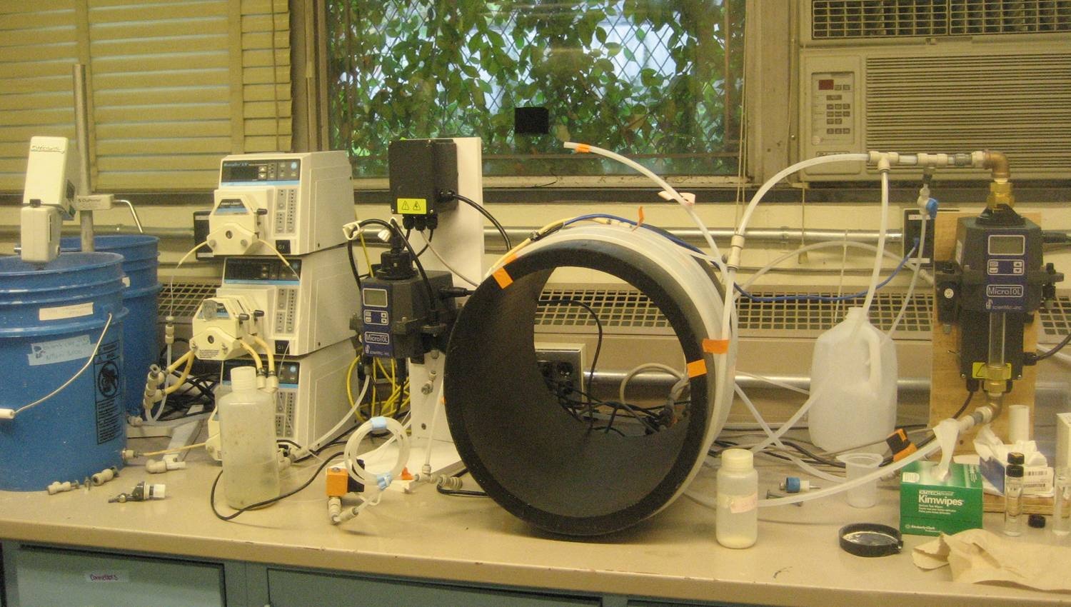
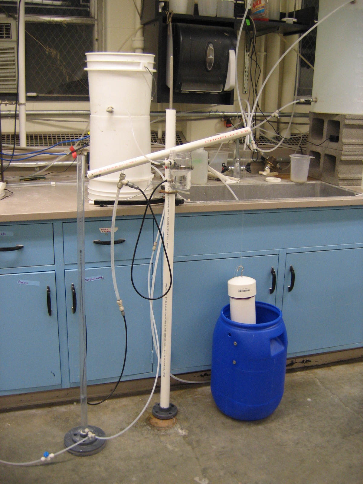
Robust ACD, picture of whole system (FCM, lever, doser, float) hooked up for testing ca. Nov 2008 | ||
| Version 1 (current) | 602 kB | user-dd1ec | Dec 09, 2008 00:32 | Robust ACD, picture of whole system (FCM, lever, doser, float) hooked up for testing ca. Nov 2008 | |||
| File IMG_7232.JPG | 513 kB | user-dd1ec | Dec 09, 2008 00:32 |
|
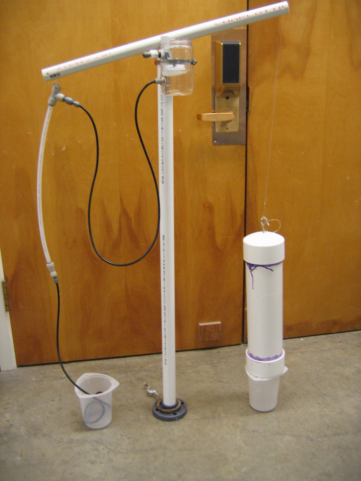
Robust ACD, picture of whole system (FCM, lever, doser, float) standing alone ca. Nov 2008 | ||
| Version 1 (current) | 513 kB | user-dd1ec | Dec 09, 2008 00:32 | Robust ACD, picture of whole system (FCM, lever, doser, float) standing alone ca. Nov 2008 | |||
| File IMG_7243.JPG | 494 kB | user-dd1ec | Dec 09, 2008 00:32 |
|
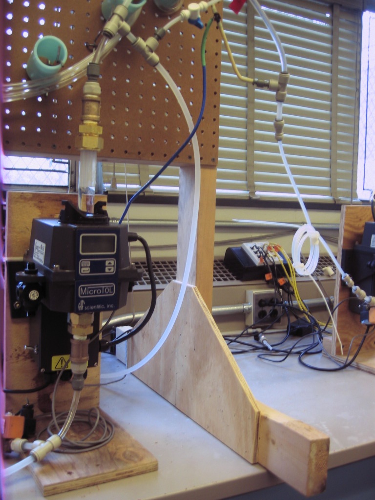
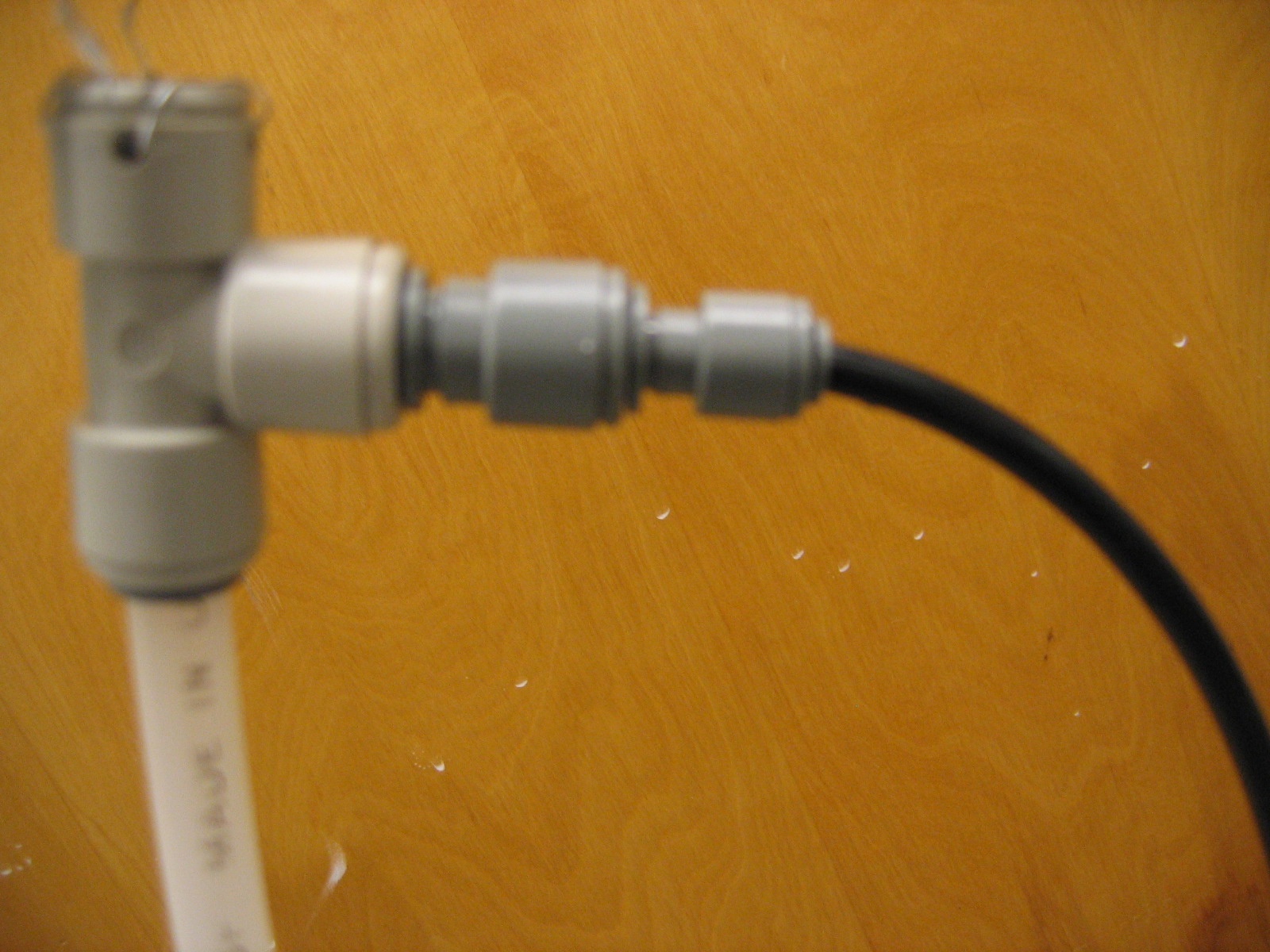
Close-up of the pressure break T connector in the robust ACD ca. Nov 2008 | ||
| Version 1 (current) | 494 kB | user-dd1ec | Dec 09, 2008 00:32 | Close-up of the pressure break T connector in the robust ACD ca. Nov 2008 | |||
| File IMG_7246.JPG | 534 kB | user-dd1ec | Dec 09, 2008 00:32 |
|
Close-up of the pivot and FCM connection in the robust ACD ca. Nov 2008 | ||
| Version 1 (current) | 534 kB | user-dd1ec | Dec 09, 2008 00:32 | Close-up of the pivot and FCM connection in the robust ACD ca. Nov 2008 | |||
| JPEG File Improvesettling1.jpg | 34 kB | user-3cacb | May 11, 2008 10:20 |
|
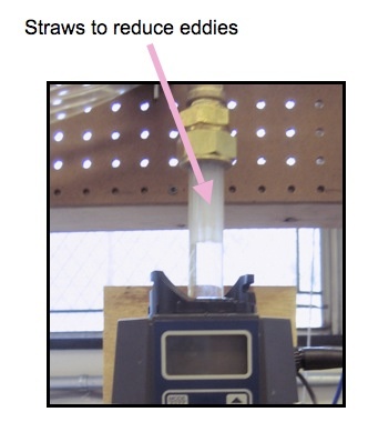
Tube Floc - Improving Settling Column by inserting straws | ||
| Version 1 (current) | 34 kB | user-3cacb | May 11, 2008 10:20 | Tube Floc - Improving Settling Column by inserting straws |
Attachments
Overview
Content Tools