 Sign-up for free online course on ANSYS simulations!
Problem Specification
1. Create Geometry in GAMBIT
2. Mesh Geometry in GAMBIT
3. Specify Boundary Types in GAMBIT
4. Set Up Problem in FLUENT
5. Solve!
6. Analyze Results
7. Refine Mesh
Problem 1
Problem 2
Step 2: Mesh Geometry in GAMBIT
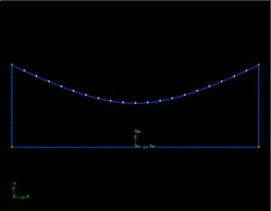
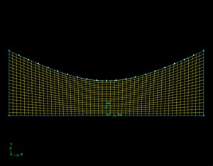
Now that we have the basic geometry of the nozzle created, we need to mesh it. We would like to create a 50x20 grid for this geometry.
Mesh Edges
As in the previous tutorials, we will first start by meshing the edges.
Operation Toolpad > Mesh Command Button  > Edge Command Button
  > Mesh Edges
Like the Laminar Pipe Flow Tutorial, we are going to use even spacing between each of the mesh points. We won't be using the Grading this time, so deselect the box next to Grading that says Apply.
Then, change Interval Count to 20 for the side edges and Interval Count to 50 for the top and bottom edges.
Mesh Face
Now that we have the edges meshed, we need to mesh the face.
Operation Toolpad > Mesh Command Button > Face Command Button 
> Mesh Faces 
As before, select the face and click the Apply button.
Save Your Work
Main Menu > File > Save
Go to Step 3: Specify Boundary Types in GAMBIT