 Sign-up for free online course on ANSYS simulations!
Step 4: Assemble and Solve Global System
Select Static under the Solver menu. This assembles and solves the global matrix. Verify that under Current Settings, the software reports Displ. done. Let's take a look at the nodal displacement values to check that they look plausible.
Nodal Displacements
Under Plotting, select Displacement. The nodal displacements are shown below.
Are the displacement boundary conditions at A and B satisfied? The displacement is largest in the middle section of the beam. Is this what you'd expect?
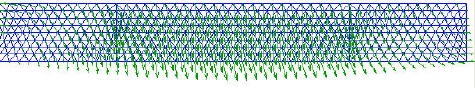
Deformed Mesh
Let's take a peek at how the elements have deformed under the applied vertical loads. Under Plotting, select Deformed mesh. Enter 1000 for the magnification factor and click OK.