 Sign-up for free online course on ANSYS simulations!
Step 2: Generate Finite-Element Model
In the introductory tutorial, we generated the mesh using the Mapping Mesh Tool. Here we'll use the CSG Mesh Tool to create the geometry and mesh it. The latter is more convenient to use especially for complex geometries while the former gives you more control over the mesh.
Strategy for Geometry Creation
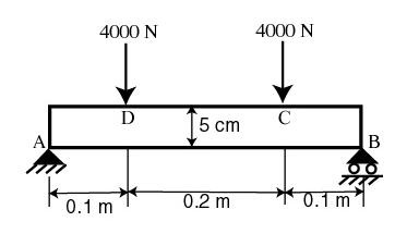
We need to apply point boundary conditions at four points A, B, C and D shown in the figure below. In redAnTS, point boundary conditions are applied to nodes. When we mesh the rectangle using the CSG Mesh Tool, nodes will automatically be created at A and B since these are corner points; the corresponding displacement BC's can be applied to these corner nodes. However, there is no guarantee that there will be nodes exactly at C and D since these are not corners. In this case, redAnTS will apply the forces at the nodes that are closest to C and D. This is possibly acceptable if the mesh is sufficiently fine.
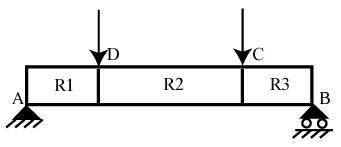
An alternative scenario is that we get clever and force C and D to be corner points. This can be done by dividing the geometry into three rectangles R1, R2 and R3as shown below. This will force nodes to be created at points C and D. Then, the point forces can be applied to these nodes. This is the strategy we'll use in creating the mesh.
Create Geometry
Under Mesh, click on Create CSGtool. This brings up the CSG Mesh Tool GUI.
Let's modify the drawing palette to help with the geometry creation. Turn on grid: Options > Grid
Enable snap to grid so that points are created exactly at grid points: Options > Snap
Change axes limits: Options > Axes Limits
<span style="color: #660099">X-axis range</span>: [-0.05 0.45]
<span style="color: #660099">Y-axis range</span>: [-0.05 0.1]
Click Apply and then Close.
Increase number of grid lines: Options > Grid Spacing ...
Unselect Auto for both x and y linear spacing.
Change X-axis linear spacing to 0.025 while retaining the axis limits: -0.05:0.025:0.45
Similarly, change Y-axis linear spacing to 0.01.
Click Apply and then Done.
Enter Draw mode: Draw > Draw Mode
Create rectangle R1: Draw > Rectangle/Square
Click approximately near (0,0) and (0.1,0.05). Don't worry about getting these points exactly right since we will edit the coordinate values as below:
Double-click on R1
Left: 0
Bottom: 0
Width: 0.1
Height: 0.05
OK
Create rectangle R2: Note the row of icons below the menu options at the top. This is referred to as the toolbar. The icons in the toolbar offer shortcuts to options in the menus.
For example, the rectangle icon ![]()
offers a shortcut for creating a rectangle and is equivalent to the menu option we used for creating R1. Click on the rectangle icon. Click approximately near (0.1,0) and (0.3,0.05) to create R2. Modify coordinates:
Double-click on R2