General Program Information
Unknown macro: {float}
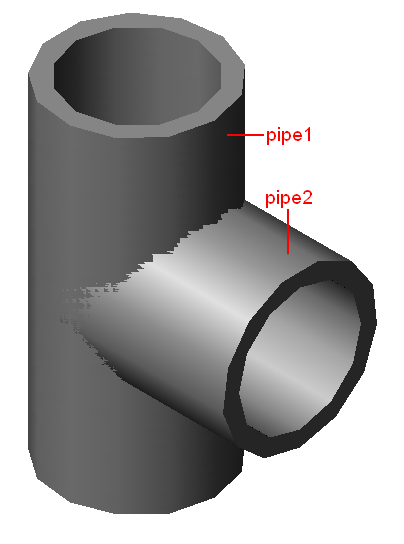
Southeast Isometric View
Input Definitions
Inputs Needed to Call the Tee Function
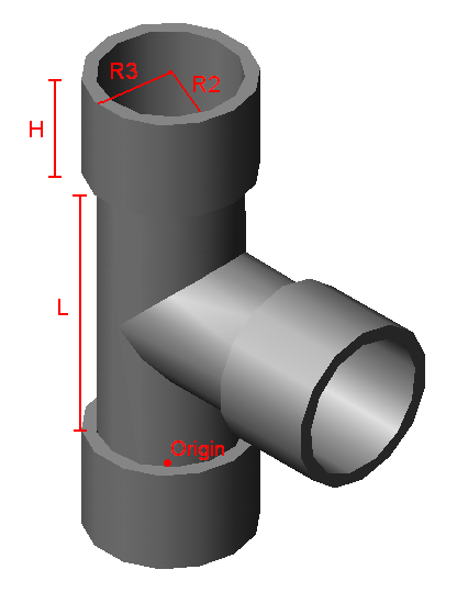
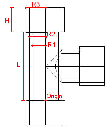
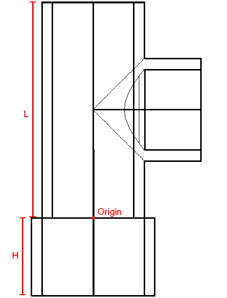
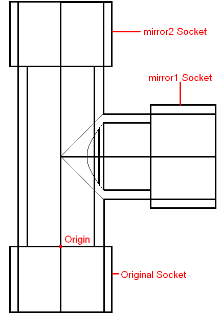
origin - A 3*1 matrix with x,y,z positions corresponding to the point where the tee will be drawn.
ND - The nominal diameter of the pipe. This value along with the pipe schedule is used to determine other actual dimensions of the tee.
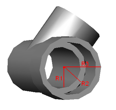
R1 - The inner radius of the main pipe.
R2 - The outer radius of the main pipe.
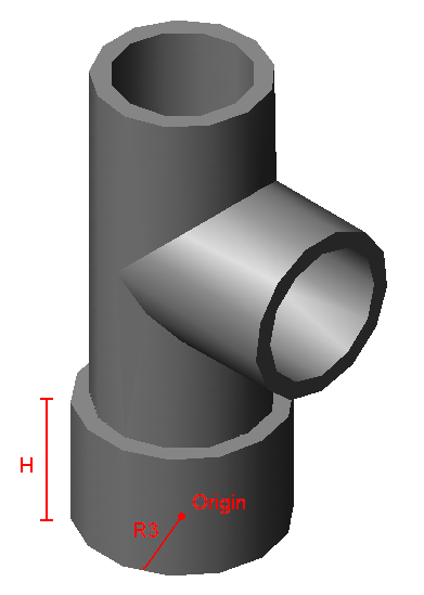
R3 - The outer radius of the sockets of the tee.
L - The length of the main pipe of the tee.
H - The length (or depth) of the sockets of the tee.
EN- The enumerated pipe schedule type. Each schedule of pipe is represented by a specific number within our code.
Inputs Defined within Pipe Database
origin-A 3*1 matrix with x,y,z positions corresponding to the point where the tee will be drawn.
ND-The nominal diameter of the pipe. This value along with the pipe schedule is used to determine other actual dimensions of the tee.
outerradius(ND)-
innerD(ND,EN)/2-
ConRadius(ND)-
ShortTeeLength(ND)*2-
SocketDepth(ND)-
EN-The enumerated pipe schedule type. Each schedule of pipe is represented by a specific number within our code.
Inputs Defined within the Tee Function
p1 =
- x : origin0
- y : origin1
- z : origin2
p2 =
- x : origin0
- y : origin1
- z : origin2 + L/2
p3 =
- x : origin0 + innerD(ND, EN)/2
- y : origin1
- z : origin2 + L/2
p4 =
- x : origin0 - R1
- y : origin1
- z : origin2
p5 =
- x : origin0 + L/2
- y : origin1 + R1
- z : origin2 + L/2
p7 =
- x : origin0 - R3
- y : origin1
- z : origin2
p8 =
- x : origin0 - R1
- y : origin1
- z : origin2 \
p9 =
- x : origin0
- y : origin1 - H
- z : -origin1 - R3
p10 =
- x : origin0
- y : origin2 + L/2
p11 =
- x : origin0 + zc
- y : origin2 + L/2 - zc
p12 =
- x : origin0 + zc
- y : origin2 + L/2
ND - The nominal diameter of the pipe. This value along with the pipe schedule is used to determine other actual dimensions of the tee.
R1 - The inner radius of the main pipe.
R2 - The outer radius of the main pipe.
R3 - The outer radius of the sockets of the tee.
L - The length of the main pipe of the tee.
H - The length (or depth) of the sockets of the tee.
win1 =
- x : origin0 - (L/2 + H)
- y : origin1 - R3
- z : origin2
win2 =
- x : origin0 + (L/2 + H)
- y : origin1 + R3
- z : origin2
EN-The enumerated pipe schedule type. Each schedule of pipe is represented by a specific number within our code.
Note: zc corresponds to the zoom constant used within AutoCAD, defined by the basics file.
Technical Program Outline
Note: All coordinates are referenced in top view in the program unless otherwise specified
Unknown macro: {float}
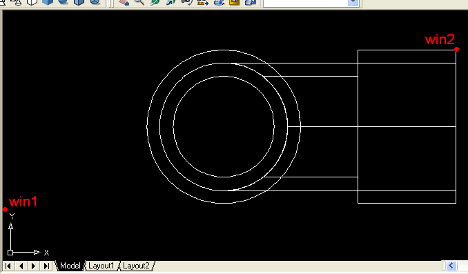
zoomwin- zooms on a window space directly around where the tee is to be drawn. The points win1 and win2 are used to select this window size, based on including the space of the tee and a zoom constant (zc) to ensure the entire drawing will be within the frame.
zoomwin <-- zoomwina(win1,win2)
win1 =
- x : origin0 - (L/2 + H)
- y : origin1 - R3
- z : origin2
win2 =
- x : origin0 + (L/2 + H)
- y : origin1 + R3
- z : origin2
Unknown macro: {float}
Southeast Isometric View
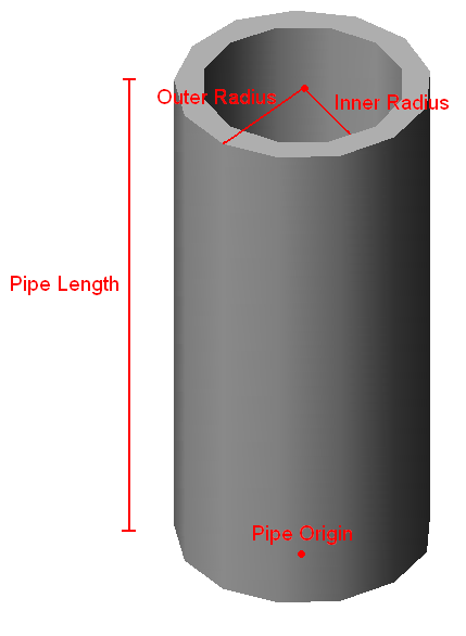
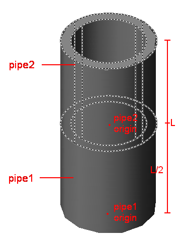
pipe1- Draws a pipe of length L, with origin at p1.
pipe1 <-- Pipe(p1,ND,L,EN)
p1 = origin
ND = The nominal diameter of the pipe. This value along with the pipe schedule is used to determine other actual dimensions of the tee.
L = The length of the main pipe of the tee.
EN = The enumerated pipe schedule type. Each schedule of pipe is represented by a specific number within our code.
Unknown macro: {float}
Southeast Isometric View
pipe2 - Draws a pipe of half the length of pipe1, with it's origin starting at L/2, the middle of pipe1. All other dimensions are the same as pipe1.
pipe2 <-- Pipe(p2,ND,L/2,EN)
p2 =
- x : origin0
- y : origin1
- z : origin2 + L/2
ND = The nominal diameter of the pipe. This value along with the pipe schedule is used to determine other actual dimensions of the tee.
L/2 = half the length of the main pipe
EN = The enumerated pipe schedule type. Each schedule of pipe is represented by a specific number within our code.
Unknown macro: {float}

Southeast Isometric View
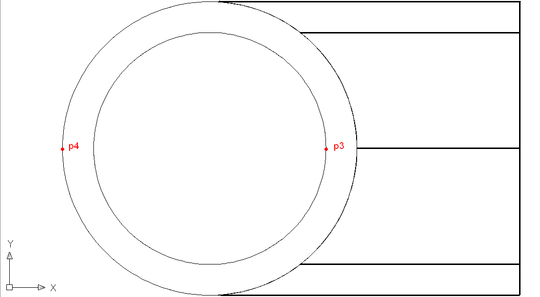
rotate1- rotates pipe2 90 degrees using p2 to select pipe2, then using p3 to specify where on the y-axis to rotate.
rotate1 <-- rotate()3d(p3,p2,"y",90)
p3 =
- x : origin0 + innerD(ND, EN)/2
- y : origin1
- z : origin2 + L/2
p2 =
- x : origin0
- y : origin1
- z : origin2 + L/2
"y" - specifies which dimension to rotate in
90 - specifies how many degrees to rotate
Unknown macro: {float}
Southeast Isometric View
union1 - unites pipe1 and pipe2 to act as one solid unit, instead of 2 separate pieces, using p4 to select pipe1 and p5 to select pipe2.
union1 <-- unionA(p4,p5)
p4 =
- x : origin0 - R1
- y : origin1
- z : origin2
p5 =
- x : origin0 + L/2
- y : origin1 + R1
- z : origin2 + L/2
Unknown macro: {float}
Southeast Isometric View
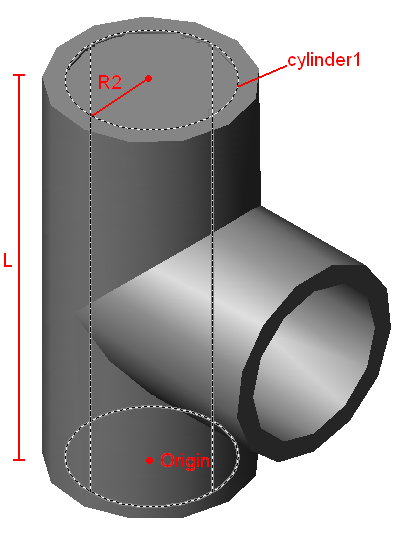
cylinder1 - Draws a cylinder of length L and a radius of R2 at the origin
cylinder1 <-- cylinderA(p1,R2,L)
p1 = origin
R2 = The outer radius of the main pipe.
L = The length of the main pipe of the tee.
Unknown macro: {float}
subtract1- subtracts cylinder1 from the tee using p4 to select cylinder1 as the object to be subtracted, and using p3 to select the tee as the object to be subtracted from.
subtract1 <-- subtractA(p4,p3)
p4 =
- x : origin0 - R1
- y : origin1
- z : origin2
p3 =
- x : origin0 + innerD(ND, EN)/2
- y : origin1
- z : origin2 + L/2
Unknown macro: {float}
Southeast Isometric View
cylinder5- creates a cylinder of depth -H and radius R3 positioned at the origin, forming the outer surface for the socket of the tee.
cylinder5 <-- cylinderC(p1,R3,-H)
p1 = origin
R3 = The outer radius of the sockets of the tee.
H = The depth of the sockets of the tee.
Unknown macro: {float}
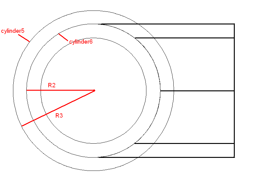
cylinder6- creates a cylinder of depth H and radius R3 positioned at the origin, forming the inner surface for the socket of the tee.
cylinder6 <-- cylinderA(p1,R1,-H)
Unknown macro: {float}
Free Rotation used to show the socket is now hollow
subtract3- subtracts cylinder6 from cylinder5 by using p to select cylinder6 as the object to be subtracted from, and using p to select cylinder5 as the object to be subtracted.
subtract3 <-- subtractA(p7,p8)
p7 =
- x : origin0 - R3
- y : origin1
- z : origin2
p8 =
- x : origin0 - R1
- y : origin1
- z : origin2
Unknown macro: {float}
viewfront- sets the workspace so that the user is viewing the object from the front
viewfront <-- viewfront
Unknown macro: {float}
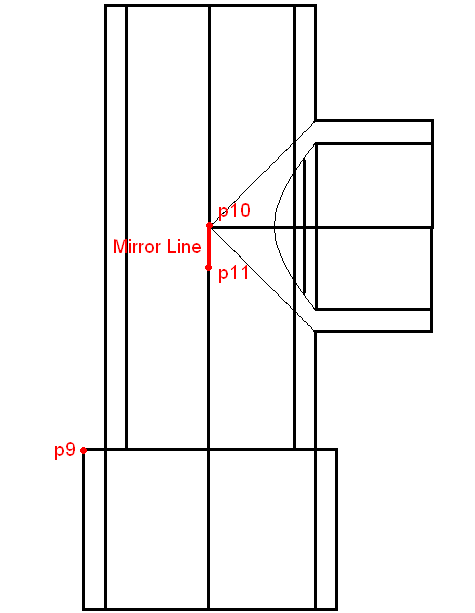
mirror1 - replicates the original socket drawn onto the orthogonal end of the tee by selecting the hollow cylinder using p9, then reflecting it over a mirror line created using p10 and p11 to give the slope and direction of the mirror line.
mirror1 <-- mirrorA(p9,p10,p11)
p9 =
- x : origin0
- y : origin1 - H
- z : -origin1 - R3
p10 =
- x : origin0
- y : origin2 + L/2
p11 =
- x : origin0 + zc
- y : origin2 + L/2 - zc
Unknown macro: {float}
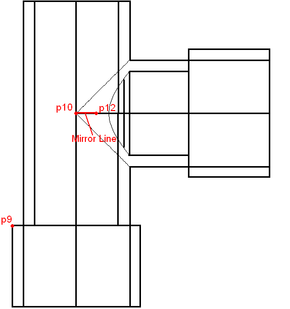
Before mirror2
After mirror2
mirror2 - replicates the original socket drawn onto the opposite end of the tee by selecting the hollow cylinder using p9, then reflecting it over a mirror line created using p10 and p12 to give the slope and direction of the mirror line.
mirror2 <-- mirrorA(p9,p10,p12)
p9 =
- x : origin0
- y : origin1 - H
- z : -origin1 - R3
p10 =
- x : origin0
- y : origin2 + L/2
p12 =
- x : origin0 + zc
- y : origin2 + L/2
Unknown macro: {float}
Southeast Isometric View
bigunion1- Unites all components of the tee to act as a single unit
bigunion1 <-- union(~)allA