 Sign-up for free online course on ANSYS simulations!
Author: Rajesh Bhaskaran, Cornell University
Problem Specification
1. Pre-Analysis & Start-Up
2. Geometry
3. Mesh
4. Physics Setup
5. Numerical Solution
6. Numerical Results
7. Verification & Validation
Exercises
Comments
Geometry
For users of ANSYS 15.0, please check this link for procedures for turning on the Auto Constraint feature before creating sketches in DesignModeler.
Set Up
First, we need to specify that the geometry is 2-dimensional. Right click the Geometry box  and select Properties . This will open the Properties of Schematic A2: Geometry Window. Under Advance Geometry Options change Analysis Type from 3D to 2D .

After the analysis type has been set, we are ready to launch Design Modeler, the geometry engine in ANSYS. Open Design Modeler by double clicking the geometry box . After launching Design Modeler, you will be prompted to choose standard units. Select Meter as the standard unit, and click OK .
Sketching
We want to sketch on the XY plane. To look at the XY plane, click the positive Z-Axis on the compass in the Graphics window.

To begin sketching, click on the Sketching tab in the Tree Outline window. To draw our domain, we will use the Rectangle tool. Click on  in the Sketching Toolboxes window. In the graphics window, draw the rectangle by first clicking on the origin (make sure the P icon is showing, meaning you are in fact selecting the point), then select a point in the 1st quadrant.

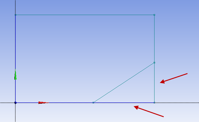
Now, we need to draw the wedge outline in the geometry. We will use the line tool to create the wedge. Select the line tool in the Sketching Toolboxes window.  Click on the points shown in the below figure. Make sure the "C" is showing.

Now, we need to remove the extraneous lines that we created. In the Sketching Toolboxes window, click the Modify tab, and select  . Next, trim the lines indicated by the figure below
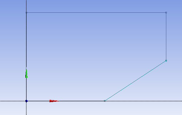
The final sketch should look like the image below
Dimensions
Next, we need to add the dimensions for the geometry. In the Sketching Toolboxes window, select the Dimensions tab. Next, select the general dimensioning tool  . To create a dimension, you first select a line. This will create a dimension for that line. Next, you will need to place the dimension next to the line. See the image below for guidance.

Next, create dimensions for the following 4 lines:

In order to add magnitudes to the dimensions, look to the Details window. You will see 4 dimensions that have been specified. Click on a dimension magnitude, and notice that the corresponding dimension will be highlighted in the graphics window. Use the following diagram to add the dimensions to the geometry.
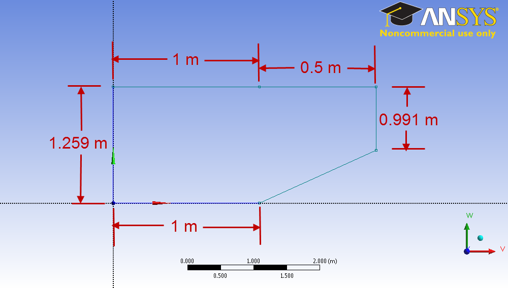
When the dimensions have been correctly applied, the geometry should look like this:

Create Surface
Next, we need to create a surface from the sketch. In the menu tool bar, select Concept > Surface from Sketches . In the graphics window, select any line of the geometry.
Next, in the details window, select Base Objects > Apply . Finally, press  . The geometry should now look like the figure below.

Create a projection
Now, we want to project the center vertical line onto the surface body we just created. This will help us with our mesh. In the menu bar, select New Sketch icon to create a new sketch

This will create a new sketch. In the Outline window, return to the Sketching tab. Again, select the tool. Draw a line from the vertex of the wedge to the top of the geometry. Make sure that when you click a vertex, a "P" appears (meaning point, constraining the line to the vertex), a "V" appears on the line (meaning vertical, putting a vertical constraint on the line), and a "C" appears when you click on the top line (constraining the newly created line to the top line). Right before you make your second click to define the line, make sure it looks like this:

The line will turn dark blue if you have done this correctly (meaning the line is fully constrained) Now, we need to create a line body from this sketch. In the menu bar, go to Concepts > L ines from Sketches . In the graphics window, select the line you just drew. In the Outline window, select Base Objects > Apply . Finally, press .
Finally, we are ready to project the line on the surface. In the menu bar, go to Tools > Projection. First, you will need to select an edge. Select the middle vertical line we just created. In the details window, select Edges > Apply

Next, we need to select the surface body for the projection. In the Details window, select Target , then select any point on the surface body.

In Details window, select Target > Apply . Finally, press . The line should now be projected on the surface. Now that we have the surface and the projection, we no longer need the line body we first created. In the Outline window, Expand 2 Parts, 2 Bodies . Right click Line Body and select Suppress Body

Now that we have completed the geometry. Save the project, and close the Design Modeler.
Go to Step 3: Mesh