 Sign-up for free online course on ANSYS simulations!
Author: John Singleton, Cornell University
Problem Specification
1. Pre-Analysis & Start-Up
2. Geometry
3. Mesh
4. Physics Setup
5. Numerical Solution
6. Numerical Results
7. Verification & Validation
Exercises
Comments
Step 6: Numerical Results
Total Deformation
First, examine the total deformation by clicking on the Total Deformation object  in the tree. Turn on the Undeformed Wireframe as shown below.
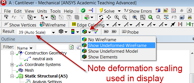
With 10 line elements, you should see the following output for the total deformation.

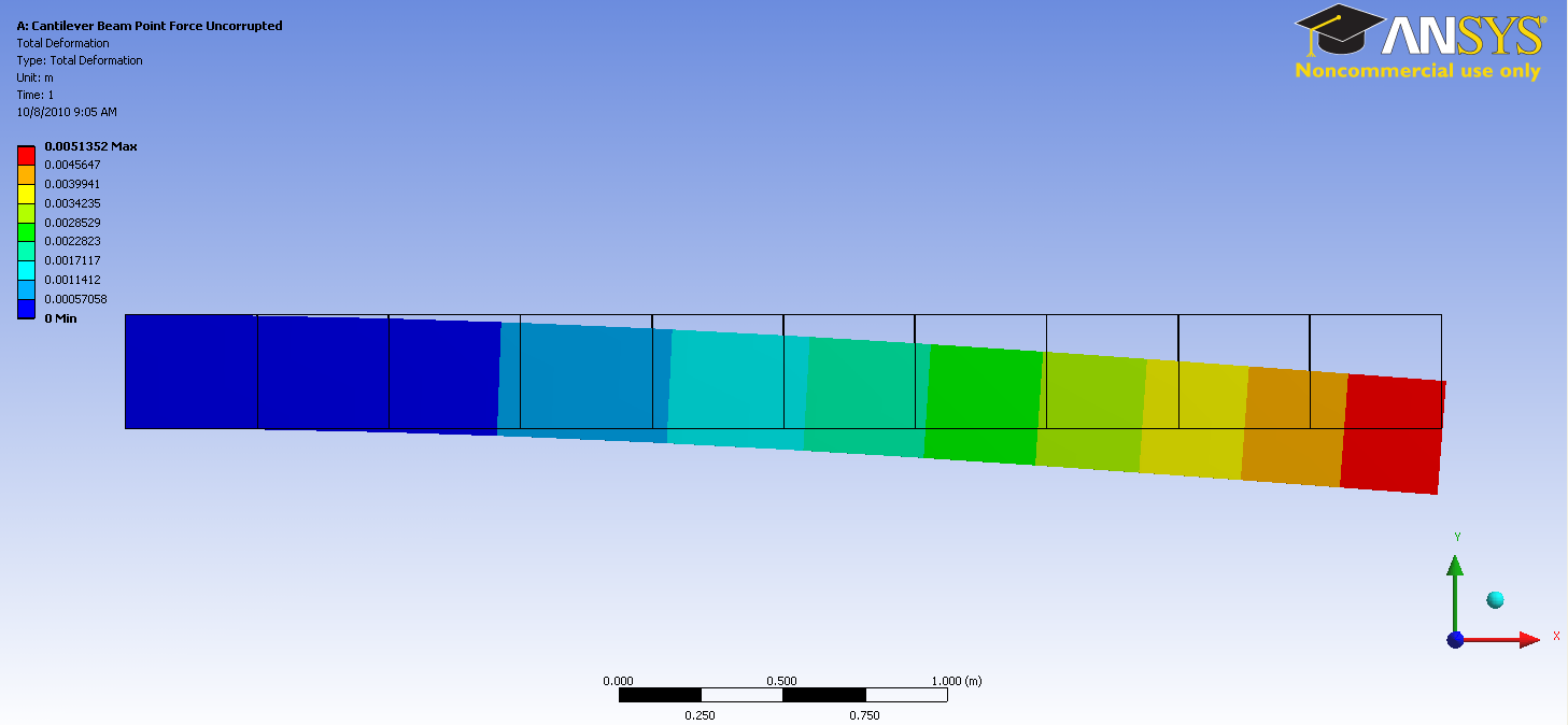
If you turn off View > Thick Shells and Beams, you will see the deformation of the line elements. The 3D beam view is constructed from this.
The beam deformation can be animated by clicking on the play button,  , which is located underneath the beam deformation results. This will interpolate between the initial undeformed and final deformed configurations.
Maximum Bending Stress
In order to examine the maximum bending stress first expand the Beam Tool folder,  , which is located under "Solution(A6)". Next, click on the Maximum Bending Stress button,
  .
.
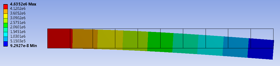
Note that in this display, ANSYS shows the same value across the cross-section. This visualization is misleading. The maximum bending stress occurs only at the top fiber. The value that ANSYS reports is 4.635 MPa which matches the value from the Pre-Analysis exactly.
Bending Moment
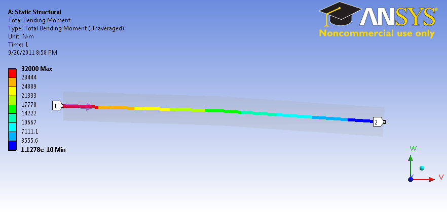
To view the bending moment along the beam, click Total Bending Moment in the Outline window. You should see the following in the graphics window.

Also notice that the values were plotted in a graph in the Graph window.

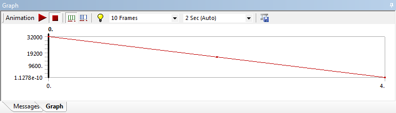
In each of the above, pay close attention to maximum and minimum values of the bending moment. At the wall, the bending moment is 32000 Nm; as the calculation for moment is
Unknown macro: {latex}
$
M = F \times d = (8000 N) \times (4 m) = 32000 \mbox
Unknown macro: { Nm}
$
Which checks out. We also notice that the minimum moment 1.1278E-10 Nm. Because this value is over 1E-14 smaller that the largest value. It can be assumed to be zero. Also, knowing that the calculation for the bending stress is:
Unknown macro: {latex}
$
\sigma_M = \frac
Unknown macro: {M times y}
Unknown macro: {I}
= 0
$
We can have some confidence in our simulation.
Directional Bending Moment
To view the directional bending moment along the beam, click Directional Bending Moment in the Outline window. You should see the following in the graphics window.

