 Sign-up for free online course on ANSYS simulations!
Author: Benjamin Mullen, Cornell University
Problem Specification
1. Pre-Analysis & Start-Up
2. Geometry
3. Mesh
4. Setup (Physics)
5. Solution
6. Results
7. Verification & Validation
8. Exercises
Setup (Physics)
Update the Project and Open FLUENT
Before we open FLUENT, we need to update the project the import the mesh into FLUENT. To do this, click Update Project  . When the project updates, double click Setup
  to open FLUENT.
Initial Settings
Before FLUENT launches, we will be prompted to set some options. In Options check the box next to Double Precision. If you have a dual processor, you can set the option under Processing Options to Parallel, and change the Number of Processes to 2. We don't necessarily need the parallel processes for this simulation as it is fairly simple, but it becomes necessary later when we refine the mesh and complicate the simulation further by changing boundary conditions.

Once the options are set, click OK.
Problem Setup - General
Now, FLUENT should open. We will begin setting up some options for the solver. In the left hand window (in what I will call the Outline window), under Problem Setup, select General. The only option we need to change here is the type of solver. In the Solver window, select Density-Based.
Models
In the outline window, click Models. We will need to utilize the energy equation in order to solve this simulation. Under Models highlight Energy - Off and click Edit.... Now, the Energy window will launch. Check the box next to Energy Equation and hit OK. We also need to change the type of viscosity model. Select Viscous - Laminar and click Edit.... Choose the Inviscid option and press OK.

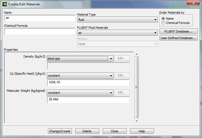
Materials
In the Outline window, highlight Materials. In the Materials window, highlight Fluid, and click Create/Edit.... this will launch the Create/Edit Materials window; here we can specify the properties of the fluid. Set the Density to Ideal Gas, the Specific Heat to 1006.43, the Molecular Weight to 28.966. When you have updated these fields, press Change/Create.
Boundary Conditions
In the Outline window, select Boundary Conditions. We will now specify each boundary condition for the simulation.
Farfield
In the Boundary Conditions window, select farfield. Use the drop-down menu to change the Type to pressure-far-field. You will be asked to confirm the change, and do so by pressing OK. Next, a dialogue box will open with some parameters we need to specify. Change the Gauge Pressure (Pascal) to 101325, and Mach Number to 3.

Also, select the Thermal tab, and ensure that the temperature correctly defaulted to 300 K. When you are finished, press OK.
Wedge
In the Boundary Conditions window, select wedge. Use the drop-down menu to change the Type to wall.
Symmetry
In the Boundary Conditions window, select symmetry. Use the drop-down menu to change the Type to symmetry.
Operating Conditions
In the Boundary Conditions window, select the Operating Conditions button. Change the Gauge Pressure to 0. Then press OK

Reference Values
In the Outline window, select Reference Values. Change the Compute From parameter to farfield. Check that the values are accurate. The reference values are used when calculating the non-dimensional results such as the drag coefficient.
