 Sign-up for free online course on ANSYS simulations!
Problem Specification
1. Pre-analysis
2. Geometry
3. Mesh
4. Setup (Physics)
5. Solution
6. Results
7. Verification and Validation
Exercises
Step 2: Geometry
Unknown macro: {composition-setup}
cloak.toggle.type = none
Unknown macro: {cloak}
Highlight each line of the above panel and insert the appropriate links to the other pages of your tutorial
Highlight the bold line at the bottom of the page that read "Go to Step...". Insert the appropriate link to the next page of your tutorial.
Enter any relevant text, images, and videos in the space under where it says "cloak" below
The Geometry of the Tertiary Truss is the most complicated part of the design process. Many hours were spent creating the Solidworks geometry for the truss. This requires much time and practice in Engineering Design. However, this tutorial focuses on properly analyzing the structure, not creating it from scratch, so we will provide the created geometry.
Click here to download the Solidworks composite .zip.
Unzip the folder, and open up ANSYS. Use the import button to open up the file "Truss K_SF_2.5_surf_Flex". (Remember to select "geometry file" from the drop down menu.) This assembly contains all the parts listed in this folder: do not separate the assembly from the parts folder.
After opening and generating the Solidworks import, you should see the entire geometry has been detailed in the window. You should take this time to familiarize yourself with the structure.
There should be 2 part groups: the Truss K-1, and the Tertiary Subframe Surface.
Truss
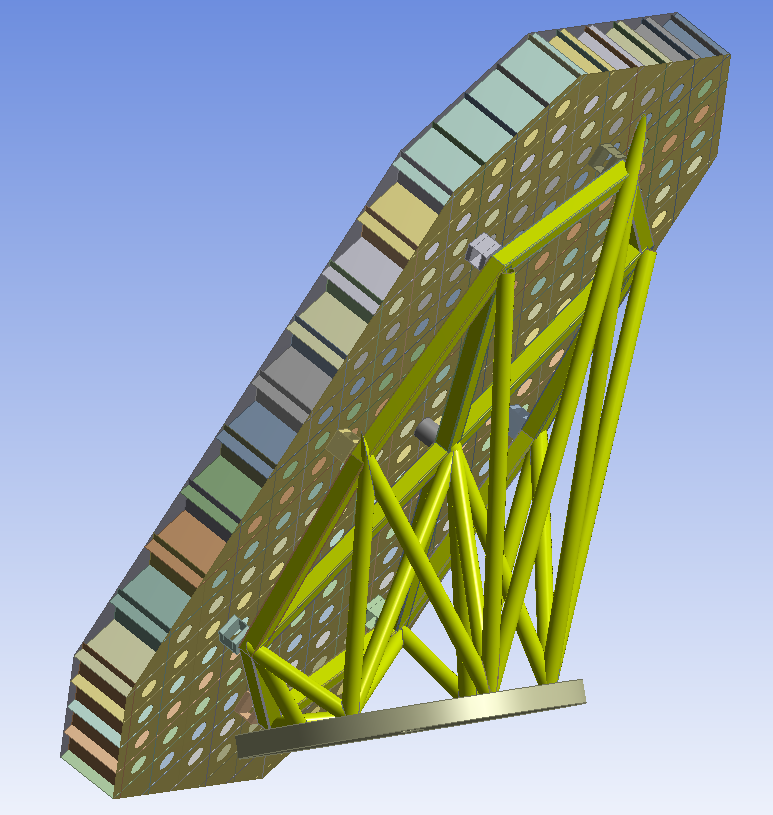
Subframe
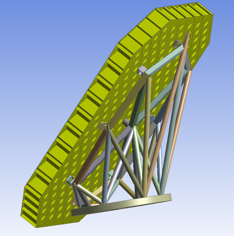
The remaining Flexure mounts and Rigid mount pad should remain separate entities.
Line Body Truss
1. Coordinate Files
If we were to directly evaluate the imported geometry, ANSYS would consider the Truss as solid body objects, and generate a highly complex mesh on each of the Truss members. This is wasted computational time. Each of the Truss members is a simple beam, and can be evaluated using beam theory. In order to tell ANSYS to compute it as such, we need to convert these members into line bodies and assign them a cross section.
The first step is to create a coordinate file detailing the end points which the curve of the line bodies will be applied to. We have split this into four files in order to visualize each section easier, rather than having it be a jumbled mess in one file. The files are provided, however, this video will detail the process through which they were made:
(video showing coordinate file creation.)
2. Creating Line Bodies
Now that the coordinate files have been created, we can use them to create the line bodies. These are the provided files. Remember to activate the cross sectional view for line bodies. View> Cross Sectional Solids. Surpress the existing Truss Part, so there is no overlap.
(video showing line body creation)
3. Cross-Sections
Once the line bodies have been created, we need to assign cross-sections to them. There are two types: the hollow cylinder and hollow rectangle.
Rectangular


Circular


The Circular cross-sections are applied to the conical and outside line bodies. The rectangular cross sections are applied to the horizontal line bodies.
(Video)
4. Rectangular Offset
If you notice, the rectangular line bodies are not touching the Flexure mounts. We need to offset the cross section so that the line body is in the correct position.
(Video)
5. Geometry Connections
For later connection-definitions, we need to define surface areas for the line bodies to connect to. The Flexure mounts have a defined surface area already, so we need to create a projection on the solid mount pad.
(video)
6. Assigning Thickness
The geometries have been assigned. It's now time to give them a thickness. 2.75e-3m
Go to Step 3: Mesh
Go to all ANSYS Learning Modules