 Sign-up for free online course on ANSYS simulations!
Unable to render {include} The included page could not be found.
Unable to render {include} The included page could not be found.
Mesh
Launch the Mesher
Now that we have completed creating the geometry of the domain, we are ready to mesh it. Return to the Project Schematic Window. In the Project Schematic window, double click the Mesh box  to launch the mesher.
Mapped Face Meshing
First we will apply a mapped face meshing. First, in the Outline window, click  to show the Mesh menu in the menu bar. In the Meshing Menu, select Mesh Control > Mapped Face Meshing. In the Graphics window, click on the domain face to select it, then in the Details window, click Geometry > Apply.
Edge Sizing
To create the edge sizings, go to Mesh Control > Sizing. Next, we need to select the edge selection filter  . Click and drag over the bottom, and top two surfaces (remember, the top surface has been split into two surfaces). The surfaces will highlight green when they've been selected. In the details window, select Geometry > Apply. Ensure that Type is set to Element Size, then change the Size from Default to
 0.05.
Now, we will create an edge sizing for the vertical edges of the geometry. Create another edge sizing, and this time, choose the left and right vertical edges of the geometry by holding Ctrl and selecting each of them, and go to Geometry > Apply. Change the Type to Number of Divisions. Next, specify Number of Divisions to 30.
Generate the Mesh
In the Mesh menu, Mesh > Generate Mesh.
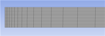
The mesh should now generate. (If you don't see it at first, select  to show the generated Mesh)
Named Selections
Next, we will have to specify names of different portions of the geometry to use in FLUENT to define boundary conditions. Make sure the Edge Selection Filter is selected before proceeding.
Inlet
Select the left, vertical edge of the geometry with a left mouse click - it should highlight green. Right click, and select Create Named Selection. Name the selection Inlet. Click OK once finished.
Centerline
Next, we will specify the axis/centerline of the pipe. Select the bottom surface of the pipe, and create a named selection. Name it Centerline.
Isothermal Wall
We will now specify the portion of the wall that is isothermal. Select the left portion of the upper surface of the pipe. Create a named selection and call it Isothermal Wall.
Heated Wall
We will now specify the portion of the wall that is heated. Select the right portion of the upper surface of the pipe. Create a named selection and call it Heated Wall.
Outlet
Finally, we will specify the outlet of the pipe. Select the right, vertical edge of the pipe. Create a named selection, and call it Outlet.


Click !update.jpb! to update all the changes made in the mesher.
We are done with the mesh creation, so we can now save the project, and close the mesher.
Go to Step 4 - Setup (Physics)
Go to all FLUENT Learning Modules