 Sign-up for free online course on ANSYS simulations!
Author: Benjamin Mullen, Cornell University
Problem Specification
1. Pre-Analysis & Start-Up
2. Geometry
3. Mesh
4. Setup (Physics)
5. Solution
6. Results
7. Verification & Validation
Mesh
Launch the Mesher
Now that we have completed creating the geometry of the domain, we are ready to mesh it. Return to the Project Schematic Window. In the Project Schematic window, double click the Mesh box  to launch the mesher.
Mapped Face Meshing
First we will apply a mapped face meshing. First, in the Outline window, click  to show the Mesh menu in the menu bar. In the Meshing Menu, select Mesh Control > Mapped Face Meshing. In the Graphics window, click on the domain face to select it, then in the Details window, click Geometry > Apply.
Body Sizing
Next, we will create a body sizing for the elements that will make up the domain. In the Mesh Menu, select Mesh Control > Sizing. Next, select the body selection filter in the menu bar

Next, select the surface in the graphics window. In the Details window, select Geometry > Apply. Now, we want to change the element size. In the Details Window, select Element Size > Default and change the value to 0.05 m.

Generate the Mesh
Now, we are ready to generate the mesh. Generate the mesh by clicking  in the menu bar or by going to Mesh > Generate Mesh. The final mesh should resemble the one in the figure below.

Named Selections
Now, we need to create named selections to use when we set boundary conditions. To create a named selection, first ensure that the edge selection filter  is selected. Next, left click on the desired edge you wish to name (multiple edges can be selected while holding down CTRL), then right click on the edge and select Create Named Selection.
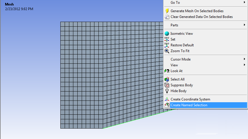
Once you select Create Named Selection, a dialogue box will appear where you will enter the desired name of the boundary. Use the diagram below to name all of the boundaries of the geometry.
