Sign-up for free online course on ANSYS simulations!
Author: Ben Mullen, Cornell University
Problem Specification
1. Pre-Analysis & Start-Up
2. Geometry
3. Mesh
4. Setup (Physics)
5. Solution
6. Results
7. Verification & Validation
Geometry
Change the Geometry Properties
In the Steady-State Thermal box, right click Geometry and select Properties. We need to allow ANSYS to recognize line bodies as valid geometries. We accomplish this by checking the box marked Line Bodies.
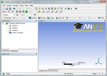
Open the Design Modeler
We are now ready to create the geometry in ANSYS. We will be creating a one dimensional line body to represent the steel bar. To open the design modeler, double click Geometry. After the design modeler is launched, you will be prompted on the default units. Select Meters and press OK.
Draw a Line
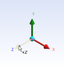
Next, we need to draw a line to represent the length of the bar. To begin sketching, we need to look at a plane to sketch on. Click on the Z-axis of the compass in the bottom right hand corner of the screen to look at the x-y plane.
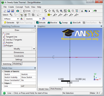
Next, click the Sketching tab in the Outline window to bring up the sketching menu. Next, select  . To draw a line, first click the origin, followed by a point on the x-axis.
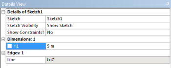
Dimension the line
Next, we need to assign the length to the line. In the Sketching Toolbox click the Dimensions tab, and select  . Click on the line to create a dimension. In the Details window, change H1 to
 5 meters.