 Sign-up for free online course on ANSYS simulations!
Error formatting macro: include: java.lang.IllegalArgumentException: No link could be created for 'SIMULATION:ANSYS 12 - Cantilever Beam - Panel'.
Step 6: Results
Total Deformation
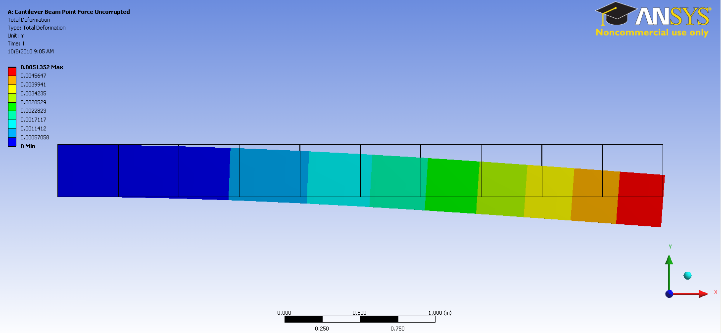
First, examine the total deformation by clicking on the Total Deformation button,  . If you have used only two elements, you should see the output shown below.

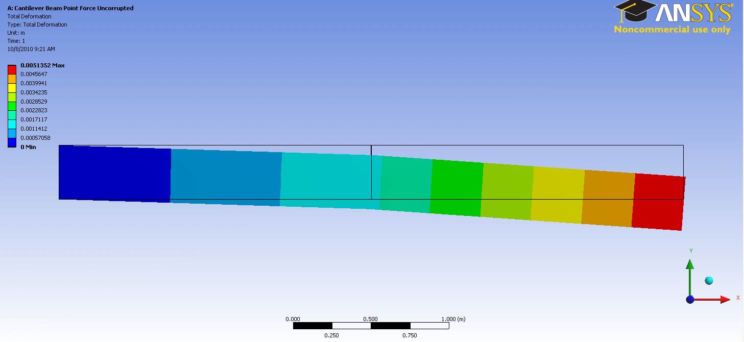
If you have chosen to use 10 elements for your mesh, you should see the following output for the total deformation.

The beam deformation can be animated by clicking on the play button,  , which is located underneath the beam deformation results.
Maximum Bending Stress
For this static structural problem, the maximum bending stress is of interest. In order to examine the maximum bending stress first expand the Beam Tool folder,  , which is located under "Solution(A6)". Next, click on the Maximum Bending Stress button,
  . If you have used only two elements, you should obtain the following output.

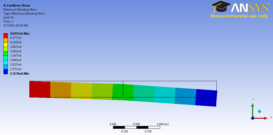
By default, ANSYS averages the stress values over the length of the beam. Using only two elements, this yields a minimum value of 2.3176e6 Pa for the maximum bending stress. This is an error created by the small number of elements used. The minimum value of bending stress should be zero because there is no moment where the force is applied. However, because ANSYS is displaying the maximum bending stress, and we are using such a small number of elements, it will not display the zero stress at the end. Next, we will verify that ANSYS is calculating the correct bending stress at the end. by displaying the bending moment. If the bending moment is zero at the application of force, then the bending stress is zero as well.
Bending Moment
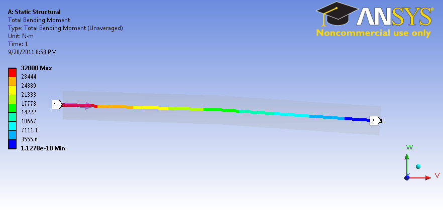
To view the bending moment along the beam, click Total Bending Moment in the Outline window. You should see the following in the graphics window.

Also notice that the values were plotted in a graph in the Graph window.

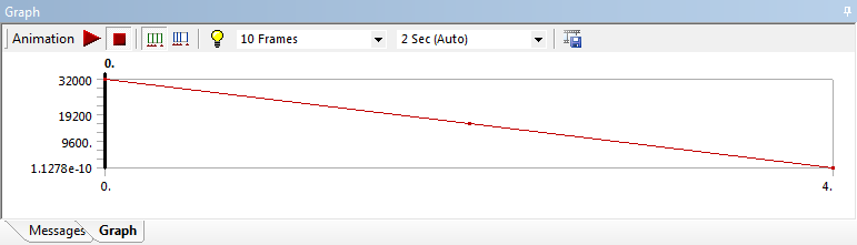
In each of the above, pay close attention to maximum and minimum values of the bending moment. At the wall, the bending moment is 32000 Nm; as the calculation for moment is
Unknown macro: {latex}
$
M = F \times d = (8000 N) \times (4 m) = 32000 \mbox
Unknown macro: { Nm}
$
Which checks out. We also notice that the minimum moment 1.1278E-10 Nm. Because this value is over 1E-14 smaller that the largest value. It can be assumed to be zero. Also, knowing that the calculation for the bending stress is:
Unknown macro: {latex}
$
\sigma_M = \frac{M \times \frac {y/2}}
Unknown macro: {I}
= 0
$
[*Go to Step 7: Verification & Validation*]
[See and rate the complete Learning Module]