 Sign-up for free online course on ANSYS simulations!
Unable to render {include} The included page could not be found.
Under Construction
This page is under construction. Please return later for updates
Setup (Physics)
Update the Project and Open FLUENT
Before we open FLUENT, we need to update the project the import the mesh into FLUENT. To do this, click Update Project  . When the project updates, double click Setup
  to open FLUENT.
Initial Settings
Before FLUENT launches, we will be prompted to set some options. In Options check the box next to Double Precision. If you have a dual processor, you can set the option under Processing Options to Parallel, and change the Number of Processes to 2.

Once the options are set, click OK.
Problem Setup - General
Now, FLUENT should open. We will begin setting up some options for the solver. In the left hand window, under Problem Setup, select General. The only option we need to change here will address the fact that pipe domain we created is axisymmetric. Under 2D Space, click the radio box next to Axisymmetric.
Models
In the outline window, click Models. We will need to utilize the energy equation in order to solve for the temperature. Under Models highligh Energy - Off and click Edit.... Now, the Energy window will launch. Check the box next to Energy Equation and hit OK.
Materials
In the Outline window, highlight Materials. In the Materials window, highlight Fluid, and click Create/Edit.... this will launch the Create/Edit Materials window; here we can specify the properties of the fluid. Set the Density to 1.2, the Specific Heat to 1000, the Thermal Conductivity to .02, and the Viscosity to 1.8e-5.
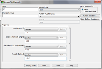
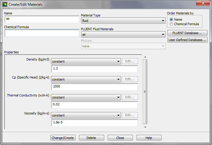
Once finished, click Change/Create, then Close.
Boundary Conditions
Now we will specify the boundary conditions governing the problem. In the Outline window, highlight Boundary Conditions.
Centerline
Under Zone, highlight Centerline. Change the Type to axis. Confirm you are changing the selection, then leave the name as the default centerline.
Heated Wall
Under Zone, highlight heated_wall. The Type should have defaulted to wall. Next, click Edit.... Click the Thermal tab, and select the Heat Flux radio button. Change the Heat Flux (w/m2) to 37.5. Click OK.
Inlet
Under Zone, highlight inlet. The Type should have defaulted to velocity-inlet. Next, click Edit.... In the Momentum tab, change the Velocity Specification Method to Components, and specify the Axial Velocity to 0.1. Click OK
Isothermal Wall
Under Zone, highlight isothermal_wall. The Type should have defaulted to wall. Next, click Edit.... Click the Thermal tab, and select the Temperature radio button. Change the Temperature (k) to 300. Click OK.
Outlet
Under Zone, highlight outlet. The Type should have defaulted to pressure-outlet. Next, click Edit.... In the Momentum tab, ensure the Gauge Pressure is 0. Click OK.
Reference Values
In the Outline window, select Reference Values. Under Compute From, select Inlet. Ensure that the values displayed are the values we specified. We are now ready to setup the solution.