 Sign-up for free online course on ANSYS simulations!
Problem Specification
1. Start-up and preliminary set-up
2. Specify element type and constants
3. Specify material properties
4. Specify geometry
5. Mesh geometry
6. Specify boundary conditions
7. Solve!
8. Postprocess the results
9. Validate the results
Step 4: Specify geometry
We'll first create keypoints corresponding to the eight vertices of the model and then generate a volume from the keypoints. The keypoints will be created in the cylindrical coordinate system. Four of the keypoints are the vertices A,B,C and D shown in the figure of the geometry. The other four keypoints have the same r and θ as A,B,C and D but are displaced in the z-direction with respect to them.
Create Scalar Parameters
For convenience, we'll create scalar parameters for the geometric dimensions in SI units.
...
R1=44e-3
R2=R1+88e-3
Z1=65e-3
Z2=14e-3
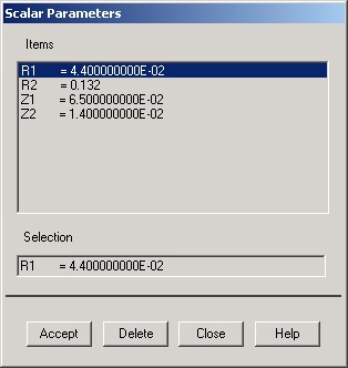
Click Close.
Switch to Cylindrical Coordinate System
Utility Menu > WorkPlane > Change Active CS to > Global Cylindrical
...
Save your work: Toolbar > SAVE_DB
Create Keypoints
Main Menu > Preprocessor > Modeling > Create > Keypoints > In Active CS
...
ANSYS reports "csys=1" at the top of the Graphics window, csys referring to the coordinate system. This is a quick way to check the current active coordinate system.
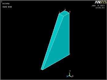
Create Volume
We'll next generate a volume from the 8 keypoints. The order of the keypoints should be around the bottom first and then the top.
...
Pick the 8 keypoints in the order in which they are numbered. Click OK in the pick menu.
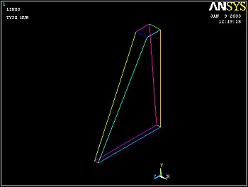
Plot Lines
Let's take a look at the lines that ANSYS generated in the volume creation process:
...
Utility Menu > PlotCtrls > Style > Background > Display Picture Background
Save Your Work
Toolbar > SAVE_DB
Go to Step 5: Mesh geometry