 Sign-up for free online course on ANSYS simulations!
...
The boundary types that you'll be able to select in the third stephttp://courses.cit.cornell.edu/fluent/plate/step3.htm depends on the solver selected. |
...
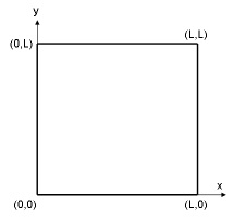
We will put the origin of the coordinate system at the lower left corner of the rectangle that defines our flow field. The coordinates of the corners are shown in the figure below:
We will first create four vertices at the four corners and join adjacent vertices to get the edges of the rectangle. We will then form a face that covers the area of the rectangle.
...
Operation Toolpad > Geometry Command Button  > Vertex Command Button
  > Create Vertex
Note that the Create Vertexbutton has already been selected by default. After you select a button under a sub-pad, it becomes the default when you go to a different sub-pad and then come back to the sub-pad. |
Create the vertex at the lower-left corner of the rectangle:
Next to x:, enter value 0. Next to y:, enter value 0. Next to z:, enter value 0 (these values should be defaults). Click Apply.
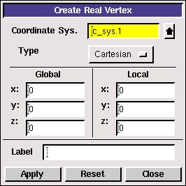
This creates the vertex (0,0,0) which is displayed in the graphics window.

In the Transcriptwindow, GAMBIT reports that it "Created vertex: vertex.1". The vertices are numbered vertex.1, vertex.2 etc. in the order in which they are created. |
Repeat this process to create three more vertices:
...
Operation Toolpad > Global Control > Fit to Window Button 
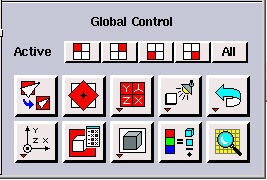
This fits the four vertices of the rectangle we have created to the size of the Graphics Window.

(click picture for larger image)
...